
Samsung Induction Cooktop NE63B8211SS Right Power Inverter Replacement
Introducción
Ir al paso 1If you get a F0 warning on your cooktop LED, it means that the main board has lot communication with the burners. It's possibe if not likely that one of your inverters is broken.
It is sometimes the case that the right inverter will be obviously fried and the main board is non-obviously fried. If this is the case, you need to replace both the inverter and the main board.
Qué necesitas
Partes
Herramientas

Ver más…
-
-
If your burners are all displaying F0, it means that the main board has lost communication with them. If your appliance is otherwise working fine (ex: you can turn on the oven), then it's likely an inverter issue.
-
Before disassembling the stove, you can try the following: Disconnect power via breaker for a minute and then power back up. In instances where the issue isn't a board, this may clear the error and restore functionality.
-
It's possible that both the power inverter and the main board need to be replaced simultaneously. If the inverter is obviously fried, start there and hope you can return the main board.
-
-
-
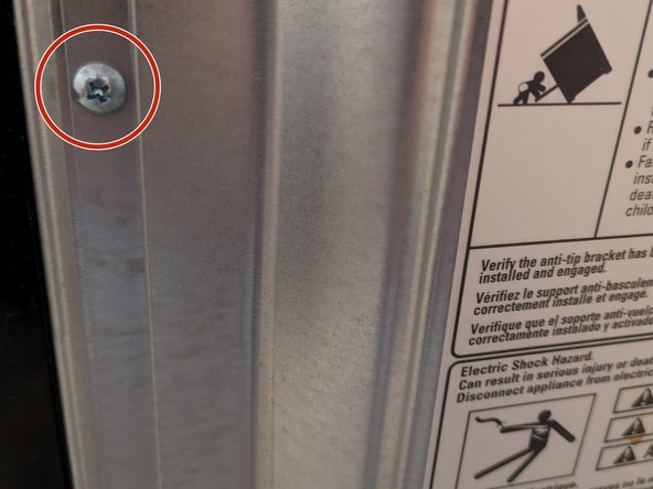
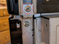
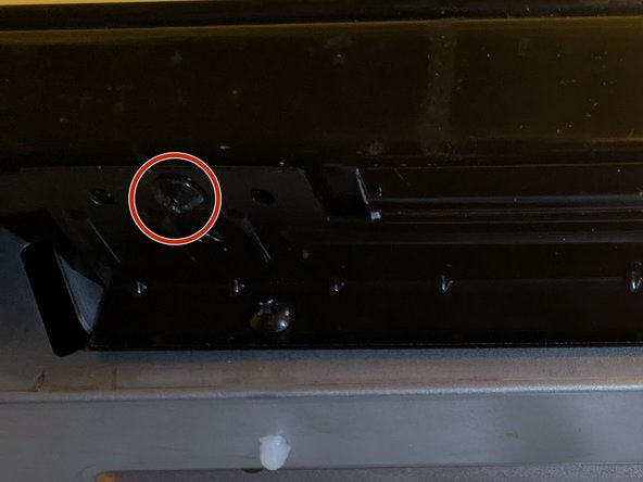
Open the oven door. There are three screws you need to remove from the front side in order to lift the cooktop
-
-
-
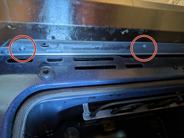
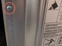
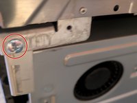
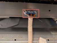
To lift the cooktop, a few screws need to be removed from the back. While doing this, also remove the backing, as it will expose harnesses that need to be unplugged for a later step.
-
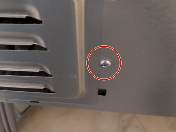
To entirely remove the backing, there are 3 screws. Two attached to the frame along the side and one attached to the vent. After these are removed, the backing simply needs to be lifted out of place.
-
-
-
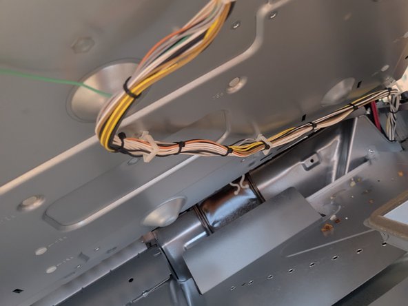
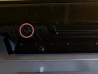
The assay also has wires that run to the back of the oven. These should be disconnected.
-
Note that there is one a plug that isn't attached to anything, this will remain that way.
-
-
-
-
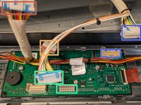
To get the cooktop isolated, the control panel needs to be detached and have its harnesses disconnected.
-
Harnesses connected to a PCB in the back and a control panel in the front are still attached. You will want to gently lift the cooktop until the screws on the left and right are exposed.
-
-
-
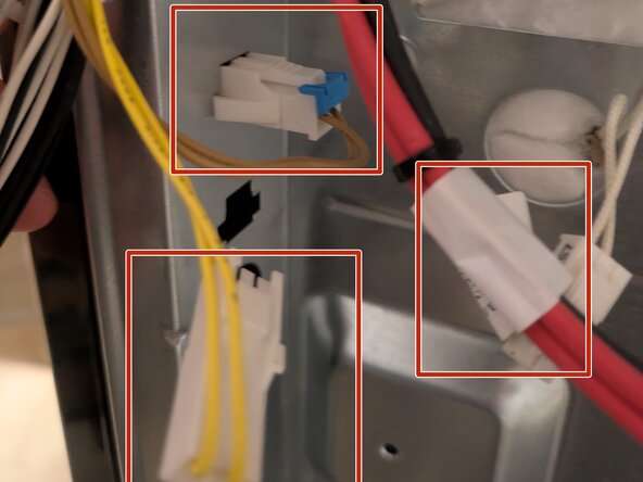
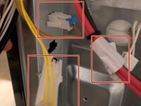
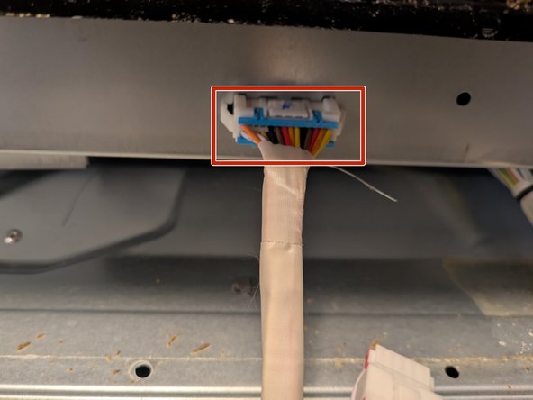
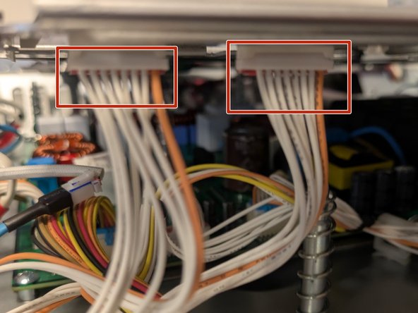
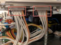
The control panel has four harnesses that need to be disconnected from the cooktop.
-
1 harness goes from the panel to the cooktop, the other 4 come harnesses lead to the back of the stove.
-
-
-
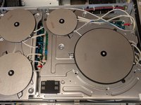
Once the harnesses have been detached, you can safely lift the cooktop from the stove. Put down a towel and place the cooktop with the glass facing down
-
There are some springs inside the cooktop that may jostle. These are large and can easily be put back in place.
-
There are 4 screws that keep the glass cooktop attached to the assay (2 on each side). Remove these four screws and then gently flip the cooktop back over. You can now remove the top.
-
At the end of this step, it is recommended to place the assay back on top of the stove and place the glass top face down on the towel.
-
When reassembling it's recommended to install with the assay and cooktop face up. Starting from the screws closer to the back of the burners was easier during reassembly.
-
-
-
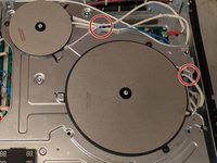
The right burners have wires that connect them to the assay. These will need to be disconnected, so the burners can be set aside and allow for proper access to the inverter.
-
The first two connections are found on top of the burners.
-
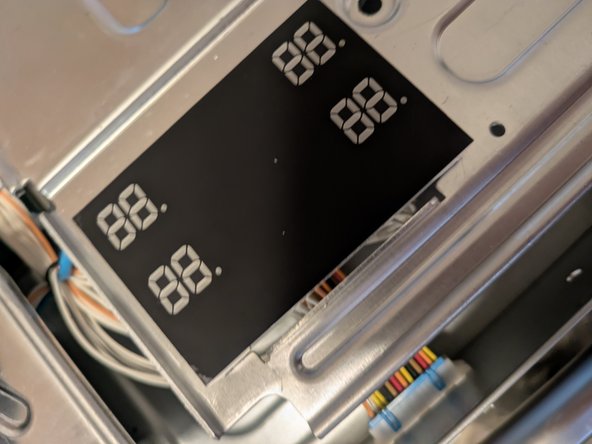
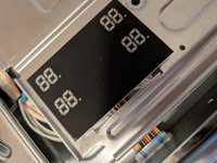
The LED panel has two harnesses to disconnect
-
-
-
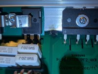
Each burner has a black and red connection connected to a terminal, disconnect these to fully disconnect the burners from the assay.
-
-
-
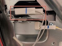
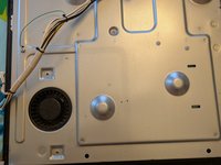
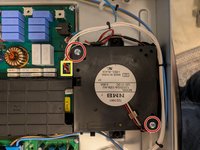
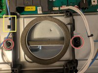
The fan for the right inverter keeps the inverter locked in place. Removing this will allow you to remove the inverter.
-
The fan housing has clips to keep the wires tight to the frame. Gently remove the wires from the clips before fan removal as they are easily broken.
-
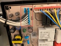
Remove the two screws and disconnect the power from the PCB. Once completed, lift the fan out of the housing.
-
Once the fan is removed, remove the screws attaching the housing to the assay. Be sure to also lift the wire out of side clip before removing the plastic housing.
-
-
-
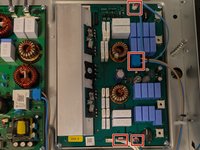
At this step, you can double check that it is in fact your inverter that is bad. There may be an obvious sign, like a scorch mark on the PCB.
-
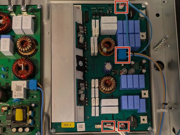
Once certain the inverter is the issue, there are four remaining harness points to unplug.
-
Once the harnesses are unplugged, remove the four screws keeping the board fixed in place.
-
There are two plastic pins that further secure the inverter. Take a pair of pliers to squeeze these down and gently lift the board off the housing.
-


To reassemble your device, follow these instructions in reverse order. Would highly recommend taking the opportunity to give every part a thorough clean before reassembling.
To reassemble your device, follow these instructions in reverse order. Would highly recommend taking the opportunity to give every part a thorough clean before reassembling.