
Elgato Stream Deck MK.1 Screen Replacement

Introducción
Ir al paso 1Replacing the screen of an Elgato Streamdeck Mk1 model number 20GAA9901, with 5x3 buttons.
Qué necesitas
Partes
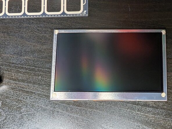
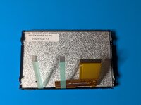
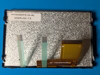
- 4.3 Inch TFT LCD Display ScreenEn venta por otro sitioYou can buy these on AliExpress for low prices, check they have 40 pins and that the ribbon layout is the same as your streamdeck. You need the non-touchscreen/non-capacitive version with a resolution of 480x282, 3.3v. They come in different brightnesses, I got a 1000nits IPS version.Ver
Herramientas


Ver más…
-
-
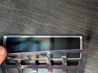
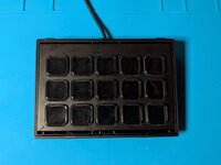
Gently pry the cover from around the buttons. It's a metal sheaf held on by clips at the top and bottom and something sticky, it's easiest to un-clip the top and then gently pry it upwards.
-
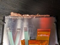
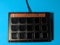
Underneath will be this metal case with copper tape near the top.
-
-
-
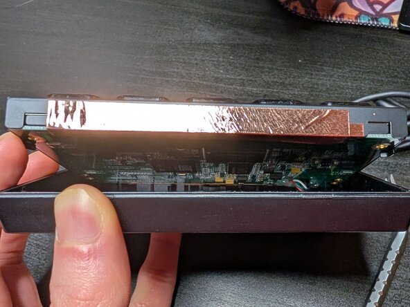
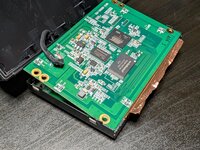
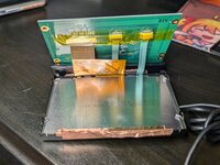
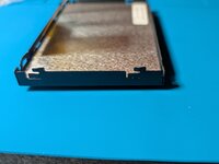
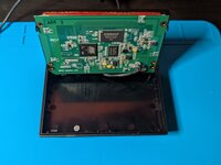
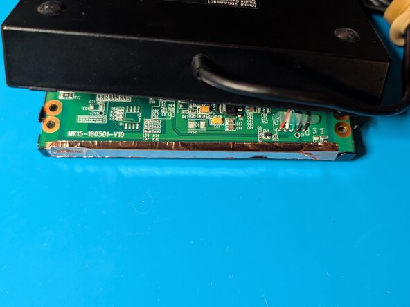
Use a prying tool to gently lift the metal container out of the shell. Directly underneath is a circuit board so try to pry on the wall rather than the bottom.
-
It will not lift-out too far because of the cables connected underneath, instead hinge it to about 70-90°.
-
-
-
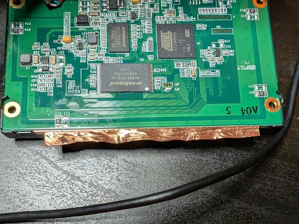
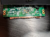
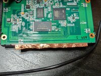
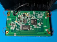
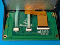
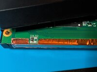
Peel back the copper tape at the top and bottom of the circuit-board.
-
-
-
Use a pair of pliers to bend these metal clips out of the way, so you can lift the circuit-board up out of it's chassis.
-
Use a prying tool to gently lift the circuit-board , there are ribbon cables connecting it to the screen underneath so don't lift too far.
-
-
-
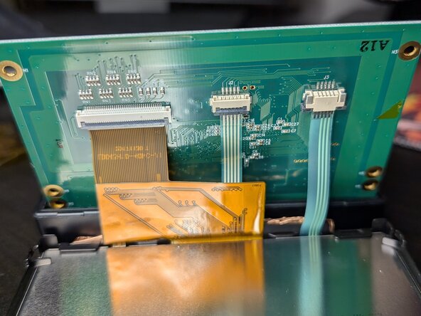
Being mindful of all the connections, lift the circuit-board out entirely of the chassis so you can access the ribbon connectors.
-
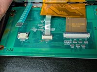
Peel off the insulator tape above the connectors.
-
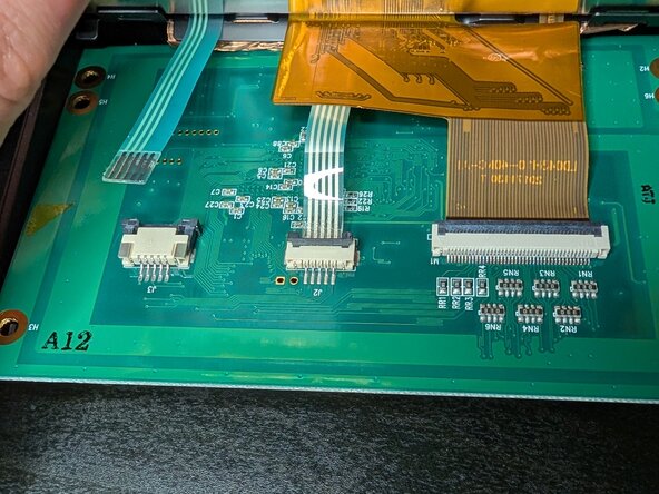
Disconnect each ribbon cable. The middle connector and the wide connector both have latches that lift/hinges upwards to release the cable. The remaining connector pulls forwards slightly.
-
-
-
Admire your newly freed circuitry and then set it aside for later.
-
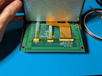
Peel back more copper tape connecting the screen to the chassis.
-
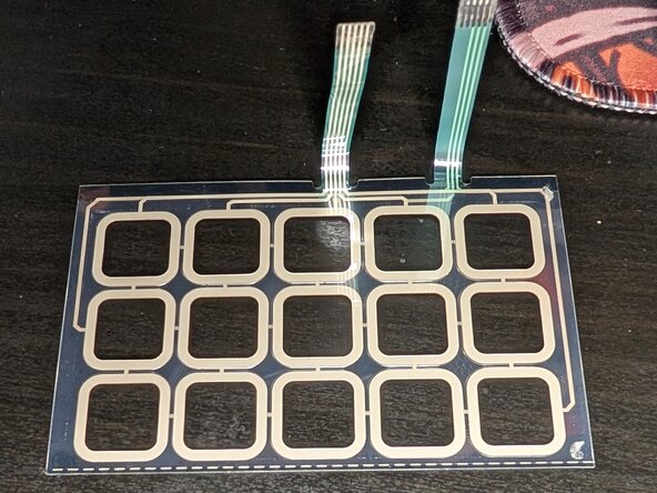
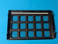
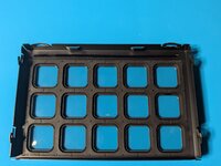
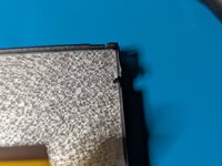
Use the pliers to again bend metal clips that are holding the screen in, then gently lift it out of the chassis.
-
There are six clips. One in each corner, plus two extras either side of the ribbon-cables.
-
-
-
-
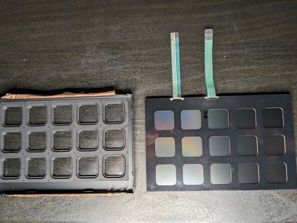
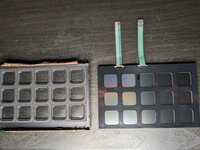
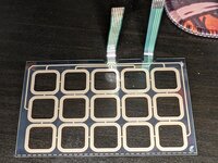
The button press-detecting grid thingy is a small thin plastic cover gently glued to the corners of the screen.
-
Gently peel it back from the screen to separate them. If there's any remaining sticky tape residue on the grid, peel it off.
-
Set the grid aside for later.
-
You have successfully liberated your damaged screen from the rest of the construction 🎉. Time to put it all back together again.
-
-
-
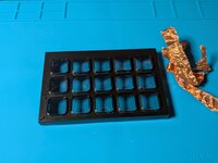
Start by cleaning up your extracted components. Remove any remaining sticky-tape, and if you're replacing the copper tape pull any remaining off the chassis.
-
-
-
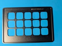
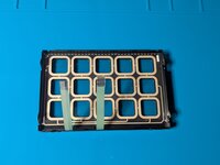
Add new double-sided sticky tape to the button chassis and insert the button-pressing-detecting grid thing. It fits flush to the top, there is a gap near the bottom where the ribbon cables are.
-
You'll know if it's upside-down because the buttons won't line up with the grid.
-
-
-
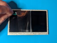
Remember to peel the protective film from your new screen, be careful not to touch it after this or you'll get fingerprints on it.
-
Insert the screen on top of the button grid, the ribbon cables should all be on the same side, and the screen fits flush with the top. (The ribbon cables are the bottom).
-
-
-
Use your pliers to gently bend the lower-half of each clip in each corner to hold the screen in place.
-
I forgot to do this here and had to go back, you also need to bend flat the two rectangular clips either side of the ribbon cables. You can do this with your finger too, be careful not to apply too much pressure to the screen though.
-
-
-
I forgot to take a picture of this, so this is from the deconstruction.
-
Add a new strip of copper tape connecting the screen to the chassis. Tuck it into the corner.
-
The purpose of this tape is for EMI protection and grounding of the screen and chassis, it's conductive so you're trying to connect the metal parts together.
-
-
-
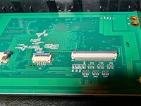
Reconnect the ribbon cables to the circuit-board.
-
Add a new strip of thermal tape to hold the ribbon cables in place. My tape is way too thin and looks dumb, you should use 1 - 2cm width tape.
-
-
-
Fit the circuit board back into the metal chassis.
-
Using your pliers bend the metal clips back over to hold it in-place.
-
-
-
On both sides re-apply the copper tape, ensure it covers half of the grounding components near the top.
-
If needed cut out a section and re-apply a small blanket.
-
-
-
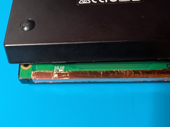
Insert the chassis back into the casing.
-
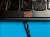
Apply a strip of copper connecting the piece from the side of the chassis, and another piece across the top.
-
These copper strips are either for grounding or EMI protection or both, point is, they have to be touching to be effective.
-
-
-
Clip the cover back onto the top.
-
It was originally also held in with sticky-tape, but I didn't bother to re-apply this to mine, it seems to hold fine.
-
You're all done :-)
-


Replacing the screen of the stream deck is relatively easy and the screen itself is a generic product that can be bought for around $10/£6 or less.
Replacing the screen of the stream deck is relatively easy and the screen itself is a generic product that can be bought for around $10/£6 or less.
