Introducción
Utiliza esta guía para refluir la soldadura en los chips que generalmente causan que la Xbox 360 tenga una falla del Anillo Rojo de la Muerte (RROD). Necesitarás la salida de alta temperatura de una pistola de calor para lograr el reflujo.
Refluir la placa base de tu Xbox 360 permite que las bolas de soldadura ubicadas debajo de la CPU, GPU, RAM y otros chips se vuelvan a conectar con sus contactos en la placa base. Para protegernos contra fallas futuras, recomendamos encarecidamente instalar nuestro Kit de reparación del Anillo Rojo de la Muerte después de completar el reflujo.
Qué necesitas
-
-
Agarra el conjunto del disco duro y presiona el botón de liberación mientras levantas su borde delantero.
-
Quita el conjunto del disco duro de la ventilación superior.
-
-
-
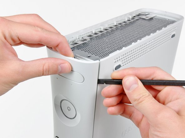
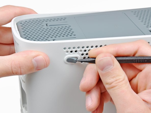
Inserta el extremo plano de un spudger o el borde de una herramienta de apertura de Xbox 360 en el pequeño hueco en el borde frontal de la ventilación inferior.
-
Levanta el borde frontal de la parte inferior de la ventilación de la placa frontal.
You can avoid this step by pulling the front cover off. Just make sure you don't break the springs for the USB bay area.
Hello, thank you ifix for this guide, I followed this guide, I got stuck at some point but I resolved it. Also I want to share this resource: Step by Step guide to fix Xbox 360 errors it helped me go through all the things associated with Xbox 360 and the troubleshooting of errors. Hope this can also help you all.
-
-
-
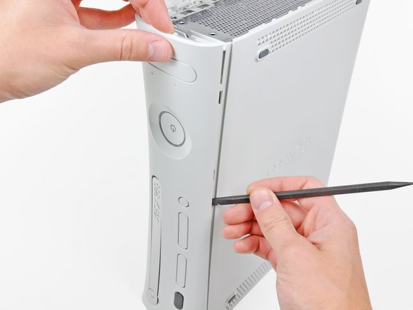
Para soltar los clips, trabaja desde el borde frontal de la ventilación inferior.
-
Mientras levantas ligeramente el borde frontal de la ventilación inferior, usa la punta de un spudger para empujar los clips lo más cerca del frontal de la ventilación inferior hacia adentro de la consola.
-
-
-
Inserta el extremo plano de un spudger entre la placa frontal y la carcasa exterior cerca del botón de encendido.
-
Pasa el spudger por el borde de la placa frontal para liberar los clips que lo sujetan al frontal de la consola.
The faceplate just pulls off, using a tool is completely unneccessary. https://beta.support.xbox.com/help/xbox-...
-
-
-
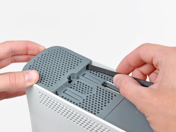
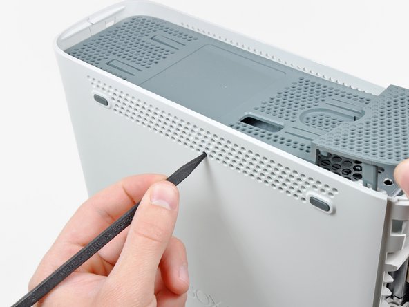
La ventilación superior está sujeta a la consola con clips. Los dos primeros clips están debajo de la ventilación superior, lo más cerca de la placa frontal, como se muestra en las fotos.
-
-
-
Inserta el extremo plano de un spudger en los pequeños huecos previamente mencionados para soltar los clips.
I found this step difficult. I wasn't able to see where the clips were from the pictures. If you look at step 14 you can see what the clips look like after the vent is taken off. Once you realize where they are it is a lot easier.
-
-
-
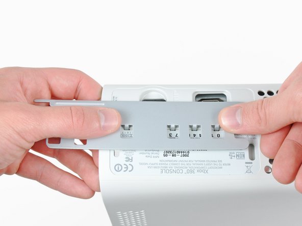
Pon la consola en vertical con el borde superior hacia abajo.
-
Con cuidado quita la etiqueta de la garantía de la consola.
LOL “Romove the warenty seal”
-
-
-
-
Presiona la herramienta de apertura de la Xbox 360 en las pestañas que sujetan la carcasa inferior a la carcasa superior cerca de los puertos de E/S.
-
Mientras presionas hacia abajo la herramienta, separa las carcasas inferior y superior para liberar las pestañas restantes.
I didn't have an XBox tool, so I followed instructions in this video for this step (https://www.youtube.com/watch?v=qaxIB6cX...) to pry it open with your fingers and a screwdriver.
The small (metal) women's hair clip is best for un-latching the tabs. The screw drivers just make the holes bigger.
You can also use the pointed end of a plastic spudger to push each clip free while you separate the case with your free hand.
-
-
-
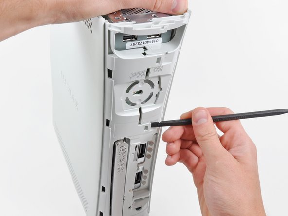
Mientras separas las carcasas superior e inferior, usa la punta de un spudger o el dedo de una herramienta de apertura de Xbox 360 para empujar la pestaña larga resaltada en rojo hacia el centro de la 360.
-
La pestaña debería soltarse, dejando las pestañas cerca del conector de corriente como la única parte que sujeta las carcasas superior e inferior juntas.
-
-
-
Usa la punta de un spudger para soltar la pestaña que sujeta el botón de eyección a la carcasa de metal.
-
Inserta el extremo plano de un spudger entre el botón de eyección y la unidad óptica
-
Apalanca el botón de eyección de sus postes de sujeción y quítalo de la 360.
-
-
-
Quita los seis tornillos plateados T10 Torx de 64 mm que sujetanla carcasa superior a la carcasa de metal.
-
-
-
Quita la cinta de metal que sujeta la unidad óptica a la carcasa de metal.
Looking at mine, I doubt it. It looks like standard foil tape
-
-
-
Agarra el conector de alimentación por sus cables y tira recto hacia afuera de su zócalo en la unidad óptica.
-
Desconecta el conector de datos SATA de su zócalo en la unidad óptica tirando de manera recta.
I found the power cable to be very tough to get out, at least it is the first time doing this.
I found it much easier to remove the SATA cable after lifting the assembly mostly out of the case.
-
-
-
Saca el conjunto de la unidad óptica de la carcasa de metal.
Be careful not to lose or break the two teeny metal clips securing the optical drive assembly snugly to the metal casing on either side of the drive's front face. I used a spudger to press in the topmost tines on these clips because they were catching on the drive and bending up. The clips should stay on the metal housing, not come off with the drive.
-
-
-
Inserta el extremos plano de un spudger en la pequeña abertura rectangular en la parte superior del conducto del ventilador de refrigeración.
-
Con cuidado suelta la pestaña que sujeta el conducto del ventilador y quítalo de la Xbox.
-
La pestaña se puede soltar alternativamente usando el dedo de metal de un herramienta de apertura de Xbox 360.
Fair warning for people using this guide for maintenance, the inside will likely have a coating of fine dust or dirt
-
-
-
Mientras levantas la tira del chasis de metal que hay encima de los ventiladores dualesm tira los ventiladores hacia el centro de la placa base.
Cleaning out the fan now, will help problems in the future.
Do Step 35 first (remove the fan connector from the motherboard), otherwise as you pull the fans forward out of the metal bracket you risk stressing the connector's attachment to the motherboard (because the fans will press against the connector as you pull them forward).
There are small black feet on the bottom of the fan assembly, You can push up from the bottom of the case if needed.
these are powerful fans. im having over heating issues with a brushless motor. anything less than a 120mm pc fan does nothing. but i must keep the top off to fit the 120 and adequate heat removal. so i wanna use tbis turbo fan and mount i ti the lid.
how do i remove the blades and get to the bearings and guts??
theres no rear access hole hiding under the specs sticker.
please help! thank
-
-
-
Utiliza el extremo plano de un spudger para soltar los clips que sujetan el escudo del módulo de RF a lo largo de la parte superior y del borde izquierdo del módulo de RF.
-
Retira el escudo del módulo RF de la consola.
-
-
-
Retira los tres tornillos Torx T8 de 5,6 mm que fijan el módulo de RF al chasis metálico.
for whatever reason the T8 screws holding the RF receiver on my unit were torqued on pretty hard. almost impossible to get off. IS taking the RF off really necessary?
They all seem like that the further down we go. Unless you're here to just repaste the board, you have to take it off
-
-
-
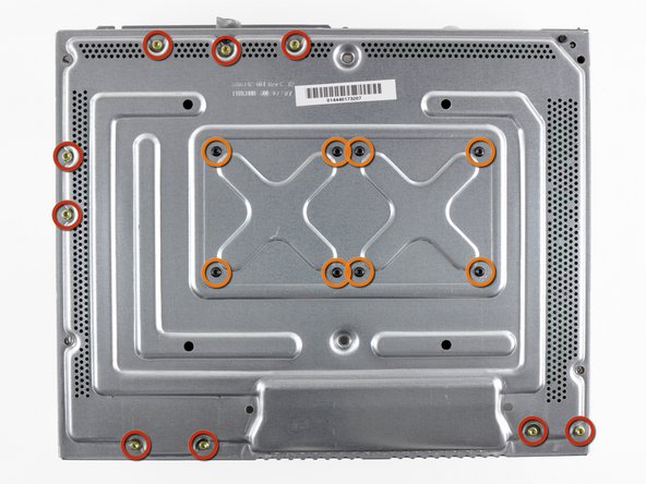
Retira los siguientes tornillos que fijan la placa madre a la carcasa metálica:
-
Nueve tornillos Torx dorados de 11 mm T10.
-
Ocho tornillos negros T8 Torx de 5.6 mm.
kinda hard for a KID to do this huh also I am a 9 year old you get it
well, it almost as if this is labeled as Difficult in the beginning!
The T8’s were T9’s on mine. This guide could be wrong, or my toolkit was mislabeled. If you can’t get the T8’s out, try a T9 before stripping the screws!
They were T8’s for me
Ryan Lee -
-
-
-
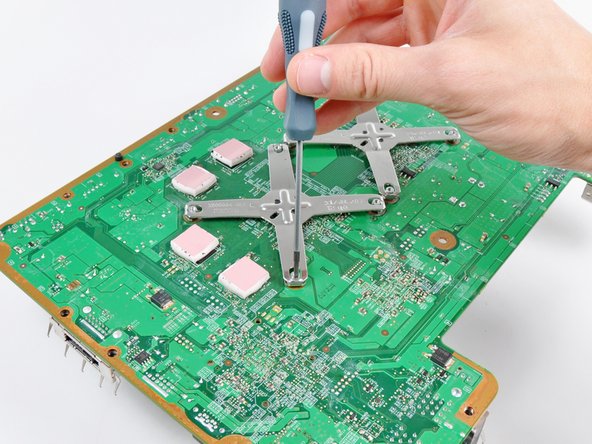
Introduce la punta de un pequeño destornillador plano entre la abrazadera en X y su poste de sujeción en el disipador de calor.
-
Haz palanca para separar la abrazadera en X de su poste de sujeción hasta que se levante por encima de la pequeña ranura cortada en el poste de sujeción.
The instructions on how to remove the x clamps are insufficient. I had a great deal of trouble with them. The small flathead screwdriver included with the kit is too small and weak to do the job. I ended up Googling other how-to's. I used a larger screwdriver and FINALLY popped them off, however as careful as I tried to be in the process I accidentally damaged a few traces around the screw hole. Repair was a failure, still have 3 red lights. Waste of time and money.
Why the heck would you suggest using a screwdriver to release the x-clamps from the motherboard, knowing that the screwdriver could slip and damage some of the traces on the motherboard!? Didn't see the comment about placing a piece of cardboard on the motherboard to prevent scratching until I had already screwed up my Xbox. How hard would it be for iFixit to develop a tool to easily remove the x-clamps like they did to open the Xbox? I wanted to do this to prevent any possibility of overheating, and went from a working Xbox to a dead one because of this bad step. Definitely took my view of iFixit down a notch, will be much more hesitant to recommend their tools and guides after this. Would like a refund but I know that's not going to happen. Super ticked!
Same thing just happened to me, the tiny screw driver they say to use has next to 0 leverage to get it off. Now my repair kit is useless cause I physically removed some of the bits because my screwdriver slipped.
Forren -
I found that inserting a sprudger between the X clamp and retaining post and turning while lifting worked well without damaging the board
The tool provided in the kit is completely incapable of performing this step (prying the X off the post).
I originally had a lot of issues prying them up; I was really worried about accidentally scratching the board. The instructions don’t seem fully adequate. Instead, first pry all four corners as high up as possible, pointing the screwdriver towards the center of the X clamp. If you pry them practically horizontally, then it makes the whole process a lot easier. Then work individually, pushing each corner slowly outwards and upwards, putting the screwdriver in from above (not the side as step 42 shows, too dangerous) into the small space between the screw and the X. Be careful at this point, just in case. Also, DON’T use the small flat head screwdriver provided; it’s too tiny to get proper leverage. I used 1/8 in. See this tutorial: https://www.youtube.com/watch?v=pHzEV3c_...
Maybe the tiny flathead in the kit I got is newer than the old ones…
DO NOT stick the screwdriver vertical as shown in step 41!
Instead use it like step 42. Insert it only that way, between each front of the X clip arm and the post, and turn it so the screwdriver turn pushes the bottom of the X clip off the post.
No risk of damaging the board this way.
Instructions were very unclear, but comments helped. Both used cardboard and the tutorial found here https://www.youtube.com/watch?v=pHzEV3c_... as mentioned by Sophia Vera. Took my time, and mostly used a longer screwdriver like in step 42. Once the first 3 clips come off, the fourth one essentially falls off, so be ready to catch your heat block when you pop the third one.
-
-
Is the x-clamp supposed to be reinstalled? It's not pictured in any part of the instructions after this point, so I did not reinstall it, and putting the xbox back together now is different than taking it apart.
The X-clamps are not reused. Since you install machine screws in place of the X-clamp mounting posts, you do not reinstall the eight screws highlighted in orange on step 41.
-
-
Inserta la punta de un pequeño destornillador de punta plana entre la abrazadera X y su poste de retención en el disipador de calor.
-
Saca la abrazadera en X de su poste de retención hasta que se levante por encima de la pequeña ranura cortada en el poste de retención.
-
Retira el disipador de calor de la CPU de la placa base. Al reinstalar el disipador de calor de la CPU, asegúrate de aplicar una nueva capa de pasta térmica.
-
-
-
Si reemplazas la placa base, transfiere las cuatro almohadillas térmicas en la parte inferior de la placa base a su nueva placa base.
-
La placa base permanece.
I'm keeping the same motherboard so do I have to replace or need the thermal pads? For this guide
Replace them if they're crusty, or you can replace them
-
-
-
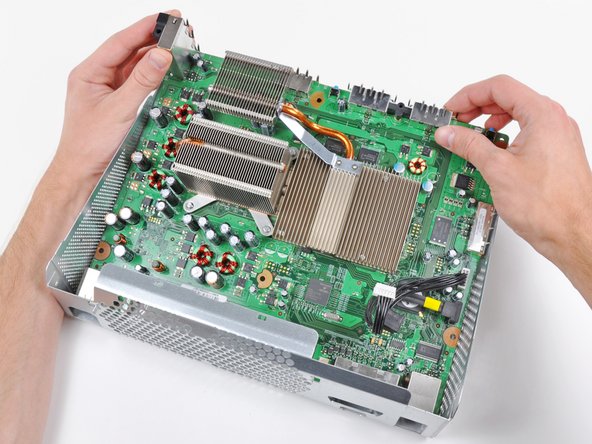
Coloca la placa base con el lado del procesador hacia abajo sobre la parte inferior metálica plana del chasis desnudo (con el lado abierto hacia abajo), como se ve en la segunda imagen. Deja que el conector USB alto cuelgue sobre el borde del chasis para que la placa quede plana.
-
Utiliza una pistola de calor en la configuración BAJA para calentar toda la parte posterior de la placa base durante un minuto. Asegúrate de pasar continuamente la pistola de calor hacia adelante y hacia atrás por la cara de la placa base para calentarla uniformemente.
Rather than using a heat gun, I have had good results using a domestic oven. Pre-heat the oven to 230C then place the motherboard in the oven component side up. I use a piece of cardboard to support the board in the oven. Heat for a couple of minutes only, you should be able to smell the flux at this time. Turn the oven off and leave for a couple of minutes, then gently crack the oven door open slightly and leave like this until cool. This sort of simulates the ramp up/hold/ramp down of the normal soldering process. I have reflowed a couple of Xbox 360 motherboards like this with good results.
Wouldn't this heat up the board uniformly? Including the capacitors? I'm thinking that is a recipe for exploding electrical components.
Joshua -
do not do this!!! only an idiot would put the whole board in the oven. i did it and the capacitors popped and micro capacitors fell off the bottom. yes i'm an idiot
Anyone performing these heating steps should really shroud the areas that don't need then heat. If you are not an expert with the heat gun it is easy to damage other parts. I recommend using silicone oven pads to lay over everything but CPU and GPU areas. There is also a danger of over heating RAM chips. The key here is an even increase in temp for a UNIFORM temp of chips. I have done about 500 of these and when I first started they would pop errors again after a few heat-ups and cool downs. I even broke a few heating too fast and too quick. Heres the deal, cover other areas, start with heat gun on low 16 inches away moving in circles move closer. Increase heat over course of 4-5 min.
-
-
-
Con la pistola de calor en posición ALTA, calienta uniformemente el área encuadrada en rojo durante cuatro minutos.
-
Después de calentar el área encuadrada en rojo durante cuatro minutos, apaga la pistola de calor y deja que la placa base se enfríe a temperatura ambiente sin moverla ni alterarla de ninguna manera.
I have a heat gun with lo (300 C) and hi (600 C) settings. I've fixed 2 PS3 YLOD (excellent IFIXIT guide for that, by the way) and have just tried to fix an XBOX using this guide. Within 2 minutes of starting , using the hi setting and keeping the gun moving , one of the dark areas around the small chips started to bubble. I haven't tested the result, yet, but suspect the worst....
I think the guide should be more informative and precise about the heat requirement.
Next time I'm going to follow the settings (lo) and timings the PS3 guide suggests.
Yeah i would not be using a heat gun on high especially for4 minutes try a good hair dryer on high should be hot enough to reflow but not so hot it will damage componets
A standard hair dryer only gets to about 200°C, which isnt high enough to melt the components on the board.
bvop -
I have heat gun, that is able to set temperature (from 50 to 600 celsius) so what is the best value for LOW and HIGH? I had seen a lot of videos on YT and read a lot of manuals, but never had found out, the correct temperature…
Well I use 420 Celsius to remove and replace electrical components on a MB for both computers and Game consoles. So why not use that temp for high and say 250-300 for low? At 420, holding it in one place over the component, it only takes about less than 1 minute to get the solder to re-flow to work it.
Here's one... i just changed out all the blown capacitors and did the entire reflow process. Plugged in the system partially assembled, just for testing purposes. Worked, no red ring. Turned it off and reassembled the entire system, plugged it in, then it red ringed... no power, no fans, nothing.
Disassembled out of shell, it turned on with no red ring. Put in a game and it worked with no issues. Assembled the top cover with only one screw in to test, it red ringed again....
What does this mean?? Makes no sense to me.
-


Para volver a ensamblar tu dispositivo, sigue estas instrucciones del Step 48 en orden inverso.
Para volver a ensamblar tu dispositivo, sigue estas instrucciones del Step 48 en orden inverso.
Cancelar: No complete esta guía.
206 personas más completaron esta guía.
Un agradecimiento especial a estos traductores:
100%

¡ Francisco Javier Saiz Esteban nos está ayudando a reparar el mundo! ¿Quieres contribuir?
Empezar a traducir ›

21 comentarios
Is there a similar guide for XBOX 360s?
Yes, there is - and It worked for me!
Dave -
What temperature ranges should I be aiming for? I have a variable temp head gun and no idea of what temperatures are best for both stages.
The heat gun they are using has a 570 F low-setting. While that doesn't give you an EXACT temperature, it should give you some idea of what they're using.
what happend
Code 0013 I followed guide and it already has the rod fix kit and still two left red lights flash
the two red rings mean it overheated and need to cool down you just had to cool it down not do all of this!
Aurelio -
Is there a tutorial for more professional tools?
Exact temperatures and times for the chip surface and the down side of the board (with K-Type thermo couppler under kapton tape) with a IR-Rework-Station, perhaps also for hot air.
With a liquid flux, a dual digital thermometer etc..
That is not "High-End" stuff, this is possible for normal people.
I think, a liquid flux is the minimum for better results.
I have this stuff, but not a "recipe".
Hi thanks for wrecking trade for repairers, however this type of fix is temporary & should be done properly by someone trained with the right equipment.
I just did this to keep my xbox going until gta 5 came out on PC no point in getting it fixed right lol.
Lmao Brian, “Big Repair” shill, the fact there is ANY controversy at all about having DIY repairs exist is astonishing!
Silly tutorial..
Why do these chips have heat sinks??? To remove heat to prolong chip life.
And you want to apply heat from a hot air gun heating chips past their rated thermal limit to the point where solder re-flows (approx. 400 degrees C) Most chips have an upward thermal limit of around 120 degrees C.
Take it to a professional do not do this yourself. Remember that the chips have internal solder connections as well so whilst your heating up the chips to reflow the solder you also run the risk of detaching the internal connections thus forever ruining the chip.
Dude, lead free solder doesn't melt until 220 *C... How are you supposed to reflow at 120... Heat from soldering does nothing to chip life, as long as you are within the manufacturers soldering heat limits. The Chip wears out from internal electrically generated heat, which is completely different. How do you think they solder GPUs to graphics cards that have a thermal limit of about 100*C.... Also 400 *C wtf... Have you ever soldered in your life? 60-40 solder melts at 188 *C
FYI I've done this 5 times to my xbox since 2008. it still works everytime after. I don't even use it anymore so theres no point in getting it reflowed with lead solder.
I did this Tutorial W/O doing the Heat Gun part and mine works great.
You should not do this. This is NOT how you reflow a board properly. You are just warping your board and causing damage. Sad that a reputable company like iFixit has this garbage on their site.
About how long does this last?
WARNING: Just replacing the drive will not make it work correctly. Microsoft has married the drives to the motherboard. Hence, in order to get full operation out of the drive you'll have to perform more steps not listed here. Search in the FAQ on this specific topic for more details. Otherwise, before buying a new drive, try cleaning the inside of the old one and/or replace the belt involved in opening and closing the drive door.
- Good Luck
Eric - Contestar
Thanks..helped!
joseph zulu - Contestar
bress the button and lift with the same hand! i thought mine was stuck because of this pic!!!
Maths with Luigi - Contestar