
Pro 13" Retina Display Mid 2014 Logic Board Replacement

Introducción
Ir al paso 1Use esta guía para reemplazar una placalogica defectuosa
No olvide constar nuestra Cómo aplicar pasta térmica antes de reinstalar el disipador de calor encima del procesador.
Qué necesitas
Partes


Herramientas


Ver más…
-
-
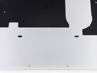
Quita los 10 tornillos que aseguran la parte inferior de la carcasa a la parte superior:
-
Dos tornillos Pentalobe P5 de 2.3 mm
-
Ocho tornillos Pentalobe P5 de 3.0 mm
-
-
-
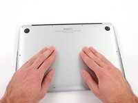
Introduce tus dedos entre la parte superior y la parte inferior de la carcasa.
-
Tira suavemente de la carcasa inferior para retirarla.
To reattach bottom case I found it helpful to line fingers up with clips under case should snap easily
If your old battery has swollen, the lower case may “pop” open. Don’t lose your screws!
-
-
I took my pointer and thumb (which are luckily long enough) to feel where the studs are on the back panel, and then as I put the back panel back on, I pushed in the spot I had marked with my fingers to ensure I was applying pressure only on this part.
If you’re doing an iFixIt battery replacement, the replacement battery has two rubber nubs which are right where the clips are that receive these studs. Folks have been saying it’s hard to get the studs to clip back in after replacement, and I had the same issue. I trimmed the top of these rubber nubs, which are a bit bigger than those on the original battery, with some side cutters. That made the fit much better.
-
A plastic foam cover also covers plug and socket and the whole battery. It is easy to remove it from the right side to the trackpad wire that the battery plug is free like shown in the picture. I kept it to use it again later.
I have done tons of these battery replacements.
You don’t need to do anything on the list after you disconnect the battery, apart from carefully moving the speakers out of the way, and then prise up the battery modules. I just very carefully, and with little even motions, use a large slot screwdriver. Being careful to keep it flat, to not puncture the battery.
Easy peasy. I have never had an issue after dozens of the tasks…
Dear Sir,
as you seem to be very much experienced with battery replacements you might perhaps give me a hint why after having removed the battery pack successfilly, the keyboard doesn't work anymore after booting the system. The Touchpad works, the keyboard backlight works but typing does not function at all.
I only disconnected the battery connector and touched nothing else. I am quite desperate …
I agree with Dave la Rose, provided you use heat rather than solvent to remove the old battery (or possibly floss, haven’t done that). Please see my comment further down this thread on how to use an iOpener for correctly heating the glue joint
After removing battery contact board plastic. My screwdriver accidentally fell and touched the battery board. And it short circuited. Now my battery doesn't charge. My laptop doesn't work without charger now. shuts after a few minutes of use. Can i fix it without sending it for repairs?
Is replacing the battery necessary?
-
-
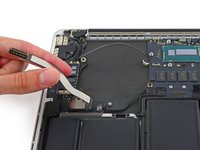
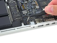
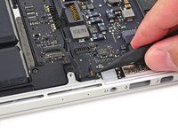
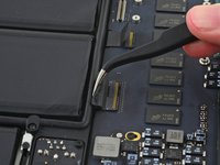
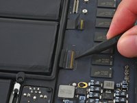
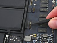
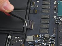
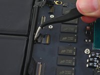
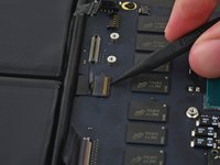
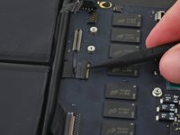
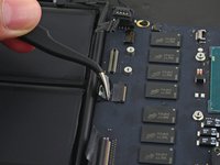
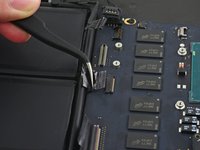
Utiliza el extremo plano de un spudger para levantar el conector de batería directamente de su enchufe en la placa lógica.
I have a friends MacBook Pro that has some water damage that caused the MacBook not to be able to use battery power, but still work when plugged into A/C. Upon further inspection I can see visible corrosion on a few of the 9 cables going from the battery connector to that small circuit board. Is it possible to just replace that circuit board?
Sometimes it can be enough to just clean the contacts without having to replace the entire board. Dosent work for complicated IC's like plcc type, where corrosion is underneath the chip. Here you will have to reheat and reapply the IC.
When placing the battery connector back into the socket on the logic board, check that every part of connector is pressed down. You should hear a soft click when it's back in place.
+1
I thought I made sure it was connected but when running the computer it only detected the battery but couldn’t power it. I had to run with power adapter. Also it didn’t charge. I guess some pins were connected but not all. To verify that all were connected I removed the plastic cover, placed it carefully completely flat, and then reattached the plastic cover. After that it worked!
Lift from the long, flat side, not the shorter side. In this picture, you should lift from the NORTH part of the connector, not the WEST side like they are doing. This is because you can spread the pressure from lifting the connector across more area, as compared to the side. I accidentally broke off part of my battery connector lifting it up the way shown, but was able to do it the way I described without problem. Make sure to lift from the wide part so you don’t have my same trouble!
The connector is no more than 1mm thick… the socket is 3-to-4mm deep so make sure you’re trying to remove the connector itself, and not pulling at the socket.
You can do it from the side like the picture, but i would recommend twisting almost like a screw driver once you have leverage under the overhanging part of the left side like in the picture. Twist the tool so that it starts to put pressure on the top, until you’ll hear it click out. You can be somewhat forceful but it shouldn’t require a lot of strength. Guiding the tool with one hand and twisting with the other is a good way to attempt this.
After I put the battery back I found out at this step that the new battery connector was off by 2 mm (because I installed my battery slightly off). Since the connector is rigid, I removed it’s plastic cover (just like we all did in Step 4) to free the cable, which allowed me to bent it enough to properly plug the connector.
Simple question: why we need to do this, I mean, disconnect battery from main board?
Well, I’m reading this step in the battery replacement repair guide, so it’s pretty critical to disconnect the battery from the main board. I’m guessing these steps are reused in other guides where disconnecting the battery might not be such an obvious need.
surf -
Also wondering the same. I came here from a link to replace the fan. Is it necessary to disconnect the battery inorder to replace the fan?
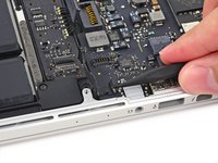
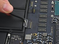
The connector wires from the battery to the connector are long
You'll have to bend them downward and into the small cove that exists so the connector can fit in place.
So use the a plastic card or flat end of the spudger to bend them downward and folded a bit back so the connector will fit in place.
Use your old battery as a guide for how they should be bent.Hi All ,
I followed the instructions step by step and changed the board successfully and reconnected everything back. When I powered it back on I can see it is charging again however it just displays a black screen and no display. Keyboard light comes on as well and the apple logo light on the back lid also turns on. Not sure what is wrong ? It has been charging for more than 15 minutes and still no joy. Anyone able to help solve or identify the issue .
Thanks
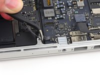
The connector cover is slightly wider and longer than the socket (<1mm) so there is a small "lip" around the top that can be used to lift it.
If your are not familiar with those repairs, and as with most of those connections, I recommend to take the time to observe your computer and the pictures from the tutorial, reading instructions and comments before starting each step. This battery connector needs both a bit of force and of precision. For a battery repair the connection of the new battery is a bit more tricky, you need to have your battery in the right position and to force it a bit the connector
Hi, I only want to remove/examine/possibly replace the left speaker as it's crackling..........I don't think I need to remove the battery connector to the logic board?
Did you get an answer to your question? I have the same thought.
-
-
If you miss or let this step for later like I did, the power left in the battery even though the computer is completely shut down, will screw up the I/O board cable like I did. I noticed this after I put all the pieces back, turn the computer on and surprise, no wifi hardware is detected. -.-
@sebasgaes, shoot, I'm only part way through the process, but I skipped this step thinking it wasn't necessary. I'm only through step 12 right now, but is there a fix if my machine doesn't recognize the wifi hardware after I've put it all back together? I don't see reference to the "I/O board cable" anywhere else in the instructions, so I'm confused about your mention of that...
UPDATE: I completed the job, rebooted, and all is well, wifi and all. Thanks anyway; gotta love iFixIt!!
jiclark -
-
-
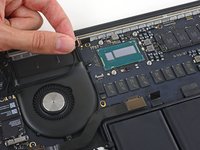
Retira con cuidado el tope de goma del ventilador del borde del disipador de calor.
For reassembly, I found it easier to loosen the lone top left 2.4 mm Phillips #000 before putting the fan bumper back in.
you need to remove the heat sink for this
-
-
-
Usa el extremo plano de un spudger para despegar las cuatro pegatinas de espuma de los tornillos del disipador de calor.
How should I reapply those little foam stickers? I guess not with normal glue.
I found that the adhesive came up with the foam except for one screw. The adhesive just stuck to the head of the screw so I left it intact as much as possible and just pressed the foam back on. It doesn’t take much to keep them in place.
If the new Logc Board coms with a heat sink attached, It is not necessary to remove the old one. Just unscrew the screw in the left corner of the heat sink and screws of the fan as well.
Est-ce grave si on les a perdu ?
The tiny rubber foam stickers help to keep the distance between the aluminium back cover and the black heat sink. I would recommend to install them or look for something similar.
-
-
-
Retira los siguientes tornillos que sujetan el disipador de calor a la placa lógica:
-
Cuatro tornillos T5 de 2,6 mm
-
Un tornillo Phillips #000 de 2,4 mm
The cross-head screwdriver bit was not the #000, the #00 was the right one.
For my mac, the cross-head screwdriver bit was not the #000, was the T5
-
-
-
Retira el disipador de calor de la computadora portátil.
I bought all the tools necessary from iFixit except for the cleaning solutions for this step. You can just use isopropyl alcohol with a microfiber cloth to clean the thermal paste off before re-applying a new coat.
-
-
-
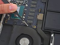
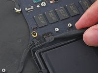
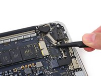
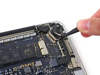
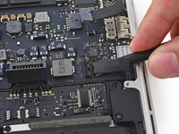
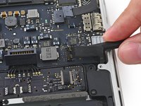
Utiliza la punta de un spudger para empujar a cualquier lado del conector del cable de la cámara para desplazarla afuera de su zócalo en la placa lógica.
Very helpful tip from Tony.
This step is very difficult. With care it could be omitted. After detach the cable from the glue on the back cover of fan, there is enough clearance to take the fan assembly out with a little pivoting, just be careful and don’t put too much stress on the table where it make a 90 downward turn to the connector. Reinstalling is just reverse and doable as well.
After readying all, trying Josh’s tip with no joy, I found that two nice sized fingernails made this easy x 2! Just push on each little indent simultaneously.
Thanks Ross! This was my 2nd time every opening a laptop and using two finger nails to push on the little indents worked amazing!
I pulled the cable directly and it got off easily.
When assembling it,just used two fingernail on two sides of the plug and pushing it back。
After all these,checked iSight working well。
Is there any hope for me? I did this step wrong and the connector came off the motherboard. Can that piece be glued back in place?
-
-
-
-
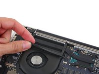
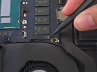
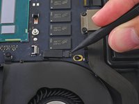
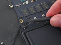
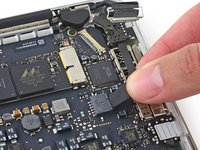
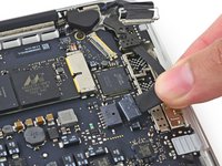
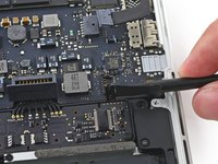
Utiliza la punta de un spudger para voltear la pestaña del conector ZIF del ventilador.
-
Jala con cuidado el cable del ventilador fuera de su zócalo.
my cable was glued, had to be pryed up first.
Take a close look at the spacing in the 3 photos. You essentially just flip the tab 90 degrees to stay vertical, then you pull the cable carefully out. When putting the new one in, no need to press hard. Just a little bit so you have that 2-3 mm spacing and then flip the tab back down.
-
-
-
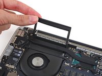
Remueve los siguientes tornillos que sujetan el ventilador a la caja superior:
-
Un tornillo T5 Torx de 5.0 mm
-
Dos tornillos T5 Torx de 3.6 mm
When reinstalling, do the screw closest to the front of the computer first.
-
-
-
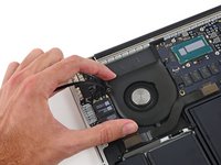
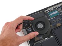
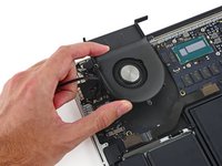
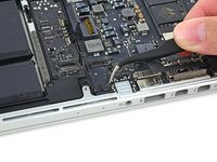
Levanta el lado del ventilador más cercano a la bisagra de la pantalla, y remueve el ventilador de la caja superior.
Um, this guide should include steps for applying thermal paste, including instructions to clean the mating surfaces, and pictures showing how much thermal paste to use.
Hi @theirongiant, there are generic thermal paste application instructions linked in the introduction “Don't forget to follow our thermal paste application guide before you reinstall your heat sink.”
Make sure to put the end furthest away from the hinge under the ribbon cable first.
Then place the hinge side. The screw furthest away from the hinge is partially obscured by the ribbon cable.
If not placed correctly, ribbon cable damage may result.
Thanks to toodarkpark, it’s the priority to connect the cable of Fan before place it on position completely.
If reverse the step, it will become ALMOST IMPOSSIBLE to insert the cable.
-
-
-
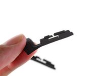
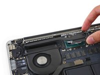
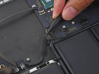
Retira los dos tornillos Torx T5 de 2,1 mm que sujetan el soporte del cable de la placa de E/S a la placa lógica.
-
Retira el soporte del cable de la placa de E/S.
-
-
-
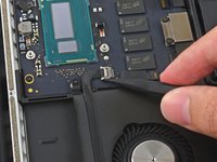
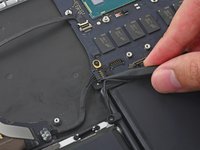
Con la punta de un spudger, empuja cualquier lado del conector de la placa de E/S para sacarlo de su zócalo en la placa lógica.
Use your fingernails to pinch the sides of the clip inwards to release the connector. I couldn’t walk it out either, both sides needed to be pushed in simultaneously to pull it out of the socket.
Do not pull from the cables end. you will risk separating thin cables from connector head. Use spudger tip to push it out.
-
-
-
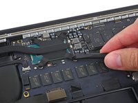
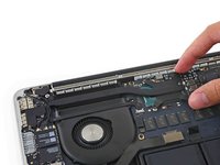
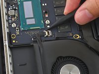
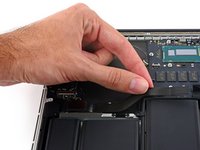
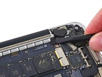
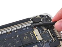
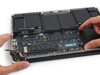
Tira del cable plano del panel táctil para sacarlo de su zócalo en la placa lógica.
I didn’t pay enough attention when I pulled the ribbon cable out, so trying to figure out how to reattach it was quite challenging for me. After searching unsuccessfully for videos/instructions on how to reattach, I finally figured out that the ribbon cable goes UNDER the black plastic part of the socket (closest to the ribbon), and then you push the little tab down to hold it in place. Hope this helps others who are struggling with this part. Otherwise, this was an amazing tutorial, and saved my macbook…
-
-
-
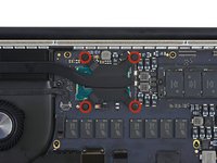
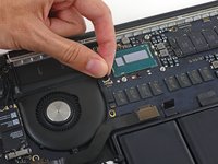
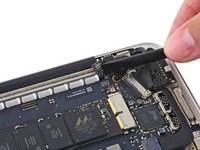
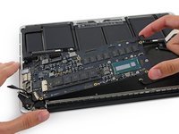
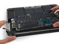
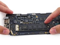
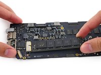
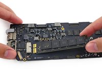
Retira el único tornillo Torx T5 de 2,9 mm que sujeta la SSD a la placa lógica.
It looks like this picture is not a 820-4924-A motherboard (A1502 2015 13in. MBPr). It must come from a previous version of Macbook pros. Don’t panic if the RAM chips on the top right corner do not look exactly the same on your board and on this picture.
The screw on my disk is ruined, i cant remove it, any suggestions?
-


Para reensamblar su dispositivo , siga estas instrucciones en orden inverso.
Para reensamblar su dispositivo , siga estas instrucciones en orden inverso.
Cancelar: No complete esta guía.
49 personas más completaron esta guía.
Un agradecimiento especial a estos traductores:
100%
¡ Jaime Salazar nos está ayudando a reparar el mundo! ¿Quieres contribuir?
Empezar a traducir ›


9 comentarios
Hi @sam !
I have a macbook pro 13" retina i5 2.6 8gb mid 2014 Model. A1502 and it has the damaged board.
In SAT, I changed it for 600 euros to replace it.
I have found a logicboard used for this same model A1502 (i7 3.0 Ghz 8Gb Ram) for half price and I would like to know if it is possible to replace it for this, or the mac will give me some problem when plugging a logicboard with different characteristics that the original?
Thanks for you support !
Was these ever answered?
Sam, thank you so much! Repair guide worked perfectly for removing logic board to clean corrosion after a water spill on the keyboard! Everything was exactly as picture and explained. I have two questions I was hoping Sam or someone else knowledgeable could answer.
1. Can/ should I replace the foam stickers from the heat sink screws (step 8)? If so, what kind of computer safe adhesive should I use to ensure that they stay in place?
2. Should the plastic cover adhered to the battery contact board in step 4 be replaced?
Hi Sam,
It is possible to remove the logic board without taking out the heat sink first? I am really not sure I can do the procedure of putting back the heat sink on reassembly with the reapplication of new thermal paste. I know that is critical in the operation of the processor which makes sure it does not burn with excessive heat. Please advice. Thanks.
i have a water damaged MBP Retina, it still works but fans ramp up to full speed immediately and it seems like it’s thermal throttling. any suggestions how to fix it ?
Guys want to ask you in this mbp efi chip is on the downside of logic board? not on the side that you face when just open the case like in the same but 15’ model, right?
And is it safe to connect battery charger while logic board is disassembled from mbp? I need it to recognize a chip
Hello! I replaced with no issues the logic board. Thanks for the guide! The only thing is, the screen is black and later middle white when get to the session screen. The HDMI port works perfectly. Any help would be appreciated. Thanks in advance!
For all the screws you use the P5 pentalobe screwdriver?
Carlos - Contestar
Pentalobe is only for the screws on the bottom cover. The Torx screw driver is for the remainder.
Fredrik -
I never, ever, ever considered using anything but the correct tool on the Pentalobe screws. Too easy to strip and void your warranty (if still in effect), as well as make it almost impossible to get inside later for another upgrade or repair. The Wiha P5 Pentalobe screwdriver fits like a glove and costs only about $11 (a fraction of your drive's price)at Amazon.com. Get it!
marketing - Contestar
I followed this exactly and was able to replace my broken trackpad. I did not have to replace the ribbon OR the battery. However I would suggest getting the ribbon since it’s fairly cheap, as for the batteries I was able to do it with a card only. I didn’t use any heat or the liquid but it takes some time. You really have to work the card in there to release the glue. Also you must be very careful not to bend the batteries or damage them, if you do you must replace with new. This took me about 1.5hrs and my computer works like new. Apple cost for this job was around $450, I did it for $120. Big ups to ifixit for this awesome tutorial, tool set and parts!
On a side note, only use quality tools, the cheap ones will break or strip the screws.
Dustin Steward - Contestar
Note that the eight 3mm screws have a shoulder under the head, while the two 2.3mm screws are “full thread”, i.e., there is no shoulder under their heads. It’s important to put the two screws with no shoulder at the hinge of the cover.
All ten screws require a P5 Pentalobe screwdriver, preferably with a magnetized tip to help hold and position the screw.
All of the screws have blue “Loctite” thread locker compound on their threads. This is to help prevent the screws from working loose and falling out. Don’t attempt to clean the Loctite from the screws — leave it in place, and it will continue to help prevent the re-inserted screws from working loose.
When replacing the bottom cover, it is a good technique to insert and BEGIN tightening all ten screws BEFORE fully tightening any one screw. After all the screws have been started, then go around and finish tightening all of them. By doing this, you make it easier to feel that each screw has been started properly, and is not “cross-threaded”.
doubleclutch - Contestar
This is what I found on my MBP mid-2014 13” Retina. All 10 used the same screwdriver. I didn’t see the blue “loctite” but I also got my computer refurbished.
Evan Shulman -
A good technique for starting to thread the screws when replacing them is to position and align the screw, and with the driver, gently turn the screw in the REMOVAL direction until you feel and hear a slight click. This click happens when the leading thread of the screw drops off of the leading edge of the thread in the hole — this is the point at which the threads are properly positioned for engagement. You can now turn the driver and screw in the TIGHTENING direction. This technique will help prevent accidental “cross-threading” of the screw, which will damage the threads permanently.
Note that this is a useful technique when installing ANY threaded fastener.
doubleclutch - Contestar
Hi peeps,
I have a wifi problem on this MBP 13” early 2015 and was pleasently surprised to find your guide to changing the airport card.
However upon closer inspection it seems that on my MBP (purchased new or so I thought) the 3 antennae seem so have been soldered together at the point where they are clamped to the chassis. I have photos but cannot post here. Can anyone conform that where the 3 antennae wires are held to the chssis by the 2 scew metal support (just before disappearing into the screen hinge), the support is not meant to short the 3 wires together. This makes no sense for 3 seperate antennae wires.
Any advice /close up photos is welcome here.
dom
colonel mustard - Contestar
Tip: Use post-it notes to keep track of screws
1. Pack of post it notes
2. Stick screws to the sticky part of the post it note
3. Write on the post it note which step and what kind of screw it is
ibash - Contestar
Hi, in order to drain the battery I am running:
yes > /dev/null
in 4 terminals, so the CPU maxes out at almost 99%.
I hope this speeds up the battery draining process.
And the backlight is at maximum brightness :-)
You can see the cpu load in Activity Monitor.
Its draining at 20% per 15 minutes.
Any concerns about draining the battery in this way?
Andre van der Ham - Contestar
Something I’ve been curious about, is it possible to upgrade a late 2013 Retina model MacBook Pro, with the improved 16gb ram and i7 processor logic board from the 2015 retina model? I’d be interested to try but not ready to shell out the $500+ to be the first lol
Chat Dawgie - Contestar
Without rehashing what others have said, I would highly recommend reading through the steps *and* the comments for each before tackling your replacement for tips. Highlights for me were: only disconnecting what actually needed to be disconnected, rotating the spudger to release the track pad cable, a hair dryer worked perfectly fine, and the pencil outline of the battery before you remove. You got this!
N DesRochers - Contestar
Installation of replacement AirPort card was easier than I had expected thanks to this guide. Thank you.
chaslaw - Contestar
I use replaced SSD and it was super easy and working great. I can finally upgrade Mac OS with plenty of room to spare and no more low memory alerts. Well worth investment and didn’t have to buy new laptop
Pete James - Contestar
It's interesting that this tutorial is rated Moderate even though you need to remove the battery. The battery removal tutorial which is basically the same but with fewer steps is rated Difficult.
Marv Ruona - Contestar
when i pulled the screws out i arranged them in the same way they were in. the top 2 middle screws appeared to be shorter than the rest. in order to keep them in place i got a square of packing tape sticky side up, taped both sides down with 2 other pieces of tape. and then put the screws head down in the order i pulled them.
Jason Wade - Contestar
Excellent instructions although checking battery and speakers aligned before fixing batteries into place is essential. MacBook good as new!
John Foreman - Contestar
I find it helpful to spread a soft, slightly fuzzy cloth (like flannel) over my workspace before doing something with small parts. It keeps screws and things from rolling or bouncing away. A towel might be too plush, though, as a screw might get lost in it.
Richard KeslerWest - Contestar
I cannot get the two screws (that are different than the other ones) out and now they’re stripped. Any idea what to do without using a drill?
Honeybee94 - Contestar
DO NOT REMOVE SPEAKER CABLES!! The connectors are fragile. Just remove speakers and bend attached cable away from battery. Same for trackpad cable connector at front side. This cable crosses the middle of the battery. Just remove the one connector on the back side - leave front side connector attached and fold cable toward front of computer out of way of battery.
Paul Lebow - Contestar
Is there a mistake in the wrench size?
When I did it I used a 1.3mm one.
ちくわちくわ - Contestar
The Dutch site fixje.nl says (see under "Welke MacBook Pro A1502 batterij kopen?") that the A1582 battery, which is for the Early 2015 version of the A1502 13-inch MacBook Pro, will fit the Late 2013–Mid 2014 versions of the A1502 13-inch MacBook Pro.
The A5182 battery has a higher capacity (6559 mAh) than the A1493 battery (6330 mAh), which is for the Late 2013–Mid 2014 models.
Can anyone confirm that the Early 2015 battery will actually fit in and work with the earlier A1502 models?
Philip Dygeus - Contestar
Just finished the battery replacement for Macbook Pro 13 in Early 2015. Followed the instructions to the letter. Everything went back together perfectly and now waiting for the battery to charge. Very appreciative of the instructions and the tools provided to do this job! Thank you iFixit!!
LOL - now considering replacing the SSD hard drive...
Abraham Wick - Contestar