
MacBook Pro 17" Unibody Camera Board Replacement

Introducción
Ir al paso 1Use this guide to replace the camera board.


-
-
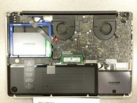
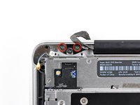
Remove the following ten screws securing the lower case to the upper case:
-
Three 13.5 mm Phillips screws.
-
Seven 3 mm Phillips screws.
-
-
-
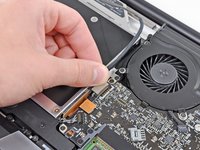
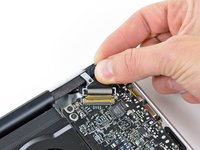
If present, grab the plastic tab attached to the battery connector and pull it toward the front edge of the device. For Late-2011 models the battery connector will not have a tab and is simply a plug that inserts straight down into the motherboard--to remove pry the plug straight up.
-
-
-
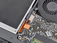
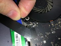
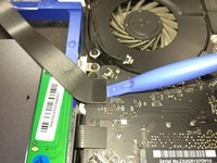
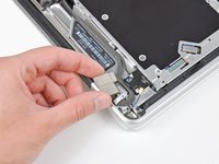
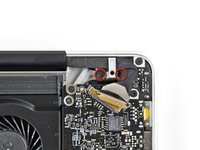
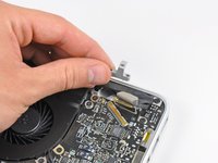
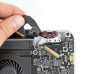
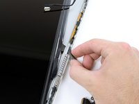
Use the tip of a spudger to push the small plastic cable retainer away from the camera cable socket for enough clearance to remove the camera cable.
-
-
-
-
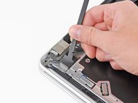
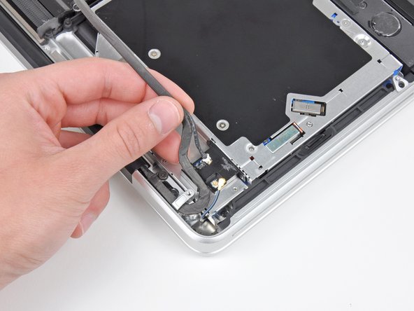
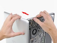
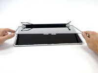
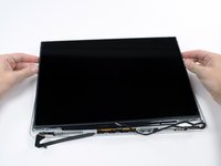
Grab the upper case with your right hand and rotate it slightly toward the top of the display so the upper display bracket clears the edge of the upper case.
-
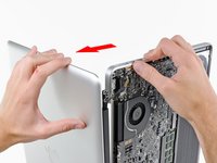
Rotate the display slightly away from the upper case.
-
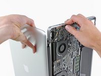
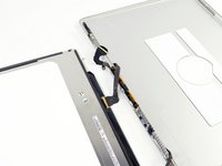
Lift the display up and away from the upper case, minding any brackets or cables that may get caught.
-
-
-
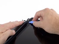
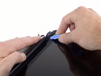
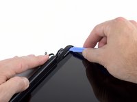
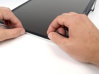
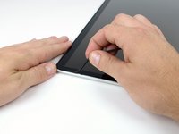
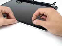
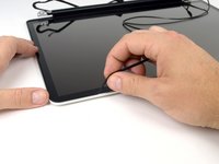
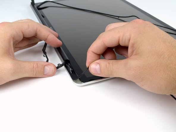
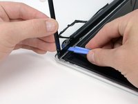
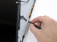
Insert a plastic opening tool underneath the black rubber gasket at the bottom left corner of the display assembly.
-
Gently pry the wide edge of the gasket up from the back case.
-
-
-
Before starting, be sure to clean the display glass with a lint-free cloth moistened with a mild solution; it will make the suction cup adhere better, and will make checking for dust on reassembly easier.
-
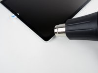
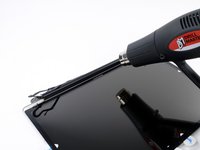
With the heat gun set to low, start by heating the outer black border near the upper right corner of the glass panel.
-
-
Herramienta utilizada en este paso:Heavy-Duty Suction Cups (Pair)$14.95
-
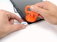
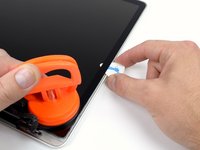
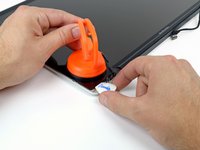
With the panel sufficiently heated, fasten a heavy-duty suction cup near the lower right corner of the display glass.
-
To attach the suction cups we sell, first position the suction cup with the movable handle parallel to the face of the glass panel. While lightly holding the suction cup against the glass, raise the movable handle until it is parallel with the other handle.
-
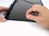
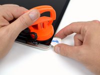
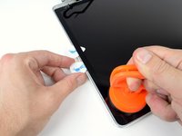
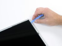
Gently lift the corner of the display glass enough to insert a guitar pick between it and the display assembly.
-
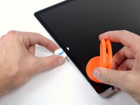
Use the guitar pick to gently pry up the adhesive securing the front glass to the display.
-
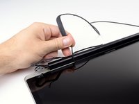
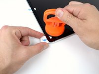
Pry up the glass panel along the right edge of the display up to the halfway point.
-
Leave the guitar pick in place halfway up the right side of the display and remove the suction cup.
-
-
-
Use a heat gun to soften the adhesive under the display glass along the right and top edges of the display.
-
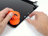
Attach a suction cup to the upper right corner of the front glass panel.
-
Pull up on the glass panel while you use a second guitar pick to separate it from the rest of the display assembly.
-
Continue working along the right edge of the front display glass until it is separated from the display.
-
-
-
Holding the clutch cover firmly, slide it towards the right display hinge.
-
-
-
Remove the four 2.3 mm Phillips #00 screws securing the LCD to the rear display bezel.
-
-
-
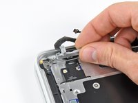
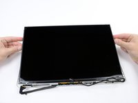
Lift one of the top corners of the LCD panel out of the rear bezel with a plastic opening tool.
-
Grasp the top corners of the LCD and rotate it upwards, slightly out of the display.
-
Pull the LCD toward the top of the display panel, freeing the screw tabs from underneath the rear display bezel.
-
-
-
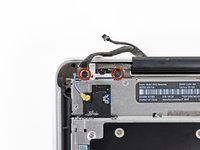
Remove the two 2.7 mm Phillips #00 screws securing the camera board to the rear display bezel.
-
-
-
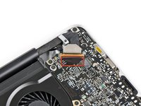
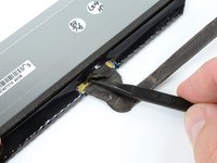
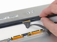
Use the flat end of a spudger to pry the camera board cable from its socket on the underside of the camera board.
-
-
-
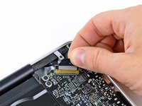
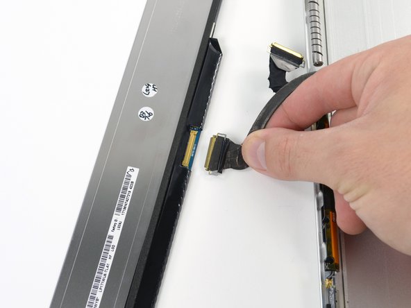
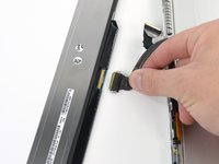
Pull the camera/AirPort cable straight out of its socket on the camera board.
-


To reassemble your device, follow these instructions in reverse order.
To reassemble your device, follow these instructions in reverse order.
Cancelar: No complete esta guía.
3 personas más completaron esta guía.

