
Canon PowerShot G16 LCD Replacement

Introducción
Ir al paso 1Please follow these steps to replace the LCD Screen. Your LCD screen may require replacement if it no longer displays an image or has been cracked or damaged.
Qué necesitas


-
-
Open the battery flap on the bottom of the camera by applying pressure and pushing in the direction of the arrow.
-
Remove your finger and allow the flap to pop open.
-
-
-
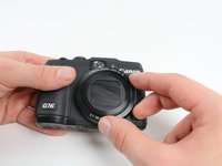
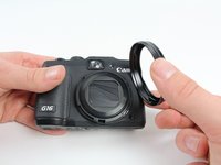
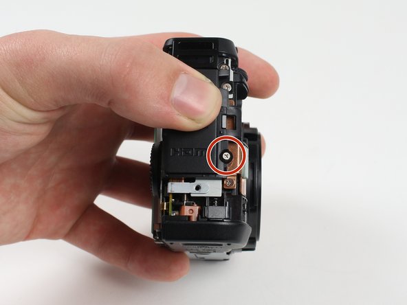
Remove the ring around the lens by simultaneously pressing the black button located at the bottom right of the ring and rotating the ring counterclockwise.
-
-
-
Herramienta utilizada en este paso:Tweezers$4.99
-
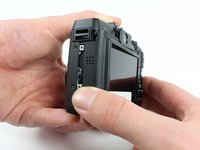
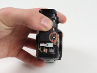
Reorient the camera so that you are looking at the back.
-
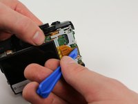
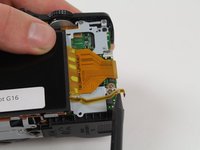
Unplug the button circuit board from the motherboard by unlocking the ZIF connector (gently lift the brown lock that keeps the cable in place).
-
Pull the connector downwards with the tweezers.
-
-
-
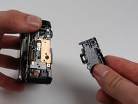
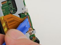
Unlock the ZIF connector for the large connector ribbon by lifting up on the brown flap with the plastic opening tool.
-
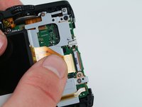
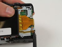
Gently pull the connector straight out of the housing with your fingers.
-


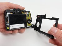


To reassemble your device, follow these instructions in reverse order.
To reassemble your device, follow these instructions in reverse order.
Cancelar: No complete esta guía.
8 personas más completaron esta guía.

Equipo

Cal Poly, Team 70-6, Forte Winter 2016 Miembro de Cal Poly, Team 70-6, Forte Winter 2016
CPSU-FORTE-W16S70G6
4 Miembros
7 Guías creadas
8 comentarios
1) Step 11 needs to be updated
2) Add Tweezers to the "tools needed" part at the beginning
Otherwise nice instruction
Nice set of instructions, although I had a real problem at step 11, and I recommend it be updated.
The instructions for step 14 should be copied-and-pasted into step 11.
Looking at the instructions for step 11, it was not at all clear that the brown lock-flap needed to be lifted first, and that the connector would then come out quite easily. Applying tweezers to the connector without first knowing about the brown lock-flap could easily lead to damaging the ribbon cable, as almost happened in my case.
So, for anyone reading this (in case the instruction set is not updated by the author), use the instructions for step 14 when you are at step 11. The connector will come out easily after the brown lock-flap is lifted, and the "connector" is NOT the grey plastic part that you see; it is in fact simply the end of the ribbon cable.
Thank You to the author. This instruction set saved me a bunch of money.
Also about step 11: Twezers may harm the cable. After opening the brown lock you can just carefully let the cable get out on step 13 while lifting the button circuit board away from the camera. On the reverse order,after replacement, twezers are needed to push the cable gently in.
Great instructions and comments, a real help however any ideas where I can get a good quality LCD please?