Introducción
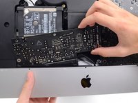
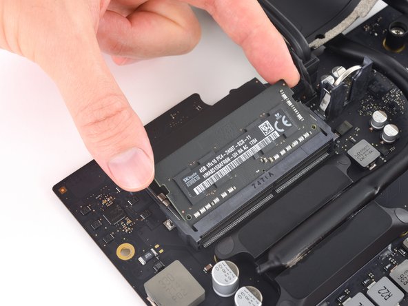
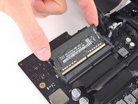
Esta guía detalla cómo quitar la placa lógica en un iMac de 21.5" Retina 4K de 2017 para remover o reemplazar la RAM.
Algunas imágenes en esta guía son de un iMac de 2015, que tiene diferencias visuales menores. Estas diferencias no afectan el procedimiento de reparación.
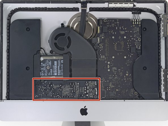
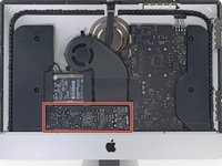
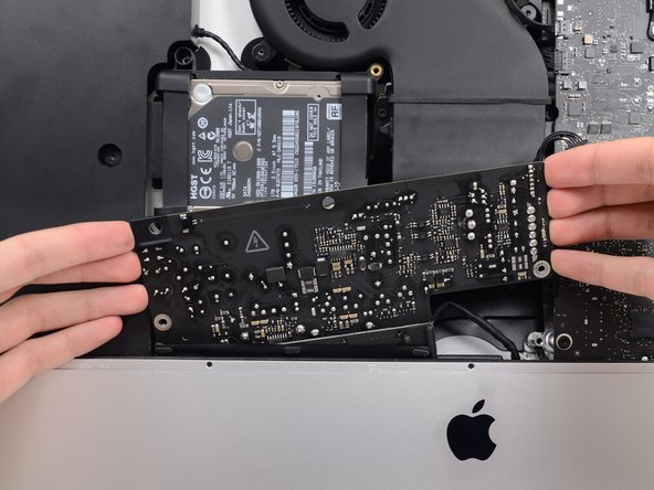
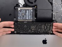
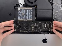
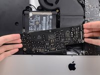
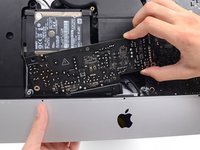
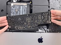
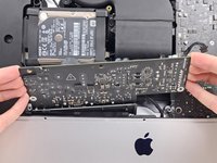
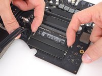
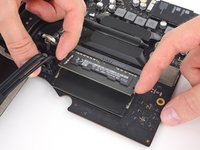
Esta guía está marcada como "potencialmente peligrosa" porque requiere que manipules una fuente de energía que contiene capacitores de gran tamaño. Desconecta el iMac y mantén el botón de encendido por al menos 10 segundos para ayudar a descargar los capacitores. Maneja la placa por los bordes para no tocar los componentes de la superficie.
Qué necesitas
-
-
Si estás utilizando la cuña de servicio de cartón iFixit, sigue estas instrucciones de ensamblaje para armarla.
-
-
Herramienta utilizada en este paso:Plastic Cards$2.99
-
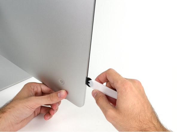
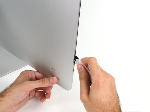
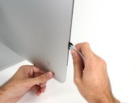
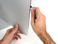
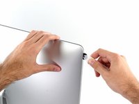
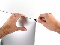
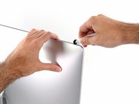
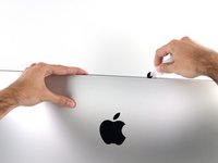
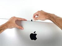
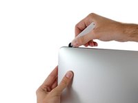
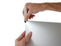
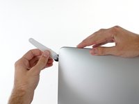
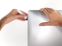
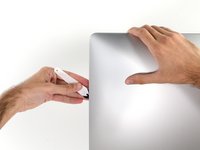
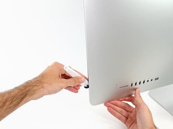
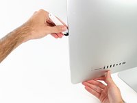
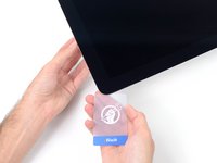
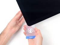
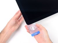
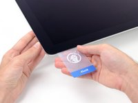
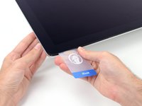
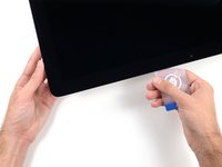
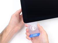
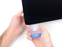
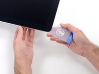
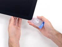
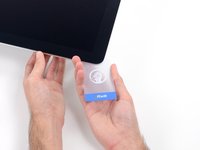
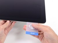
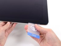
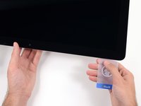
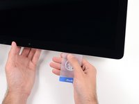
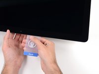
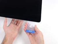
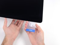
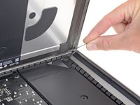
Comenzando desde la esquina superior derecha del iMac, coloca una tarjeta de plástico entre la pantalla y el marco.
-
-
-
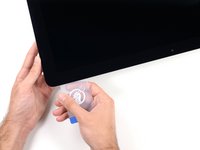
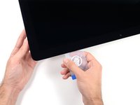
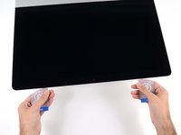
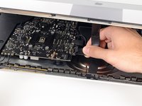
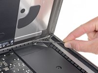
Toma la lengüeta pequeña al final de una de las tiras adhesivas de la pantalla del borde inferior y tira del adhesivo hacia la parte superior del iMac para quitarlo.
-
Repite este paso con la otra tira adhesiva y retírala.
-
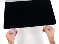
Si cualquiera de las tiras adhesivas se rompe antes de quitarla, usa una tarjeta de plástico para cortar el adhesivo restante.
-
-
-
-
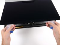
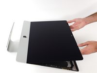
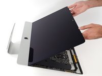
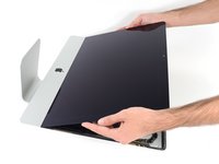
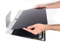
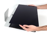
Levanta la pantalla del marco y retírala del iMac.
-
Puede ser necesario levantarlo lentamente de un lado para pelarlo contra el adhesivo restante.
-
Durante el reensamblaje, dirígete a nuestra guía de adhesivos para pantallas para instalar el nuevo adhesivo.
-
-
-
Retira los siguientes cinco tornillos Phillips que sujetan el soporte de soporte inferior en su lugar:
-
Cuatro tornillos de 3.2 mm
-
Un tornillo de 1.7 mm
-
-
-
Retira los siguientes tornillos Torx T10 que aseguran los soportes del disco duro al iMac:
-
Dos tornillos de 21 mm.
-
Un tornillo de 9 mm.
-
Un tornillo de 27 mm.
-
-
-
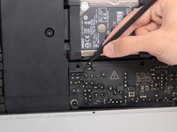
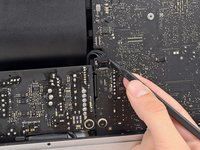
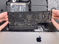
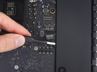
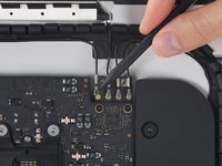
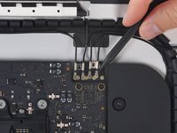
Usa la punta de un spudger para empujar cada lado del conector del cable del botón de encendido y sácalo suavemente de su zócalo.
-
-
-
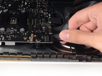
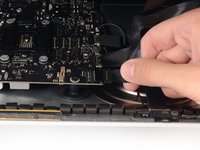
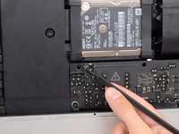
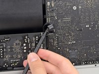
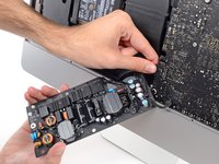
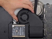
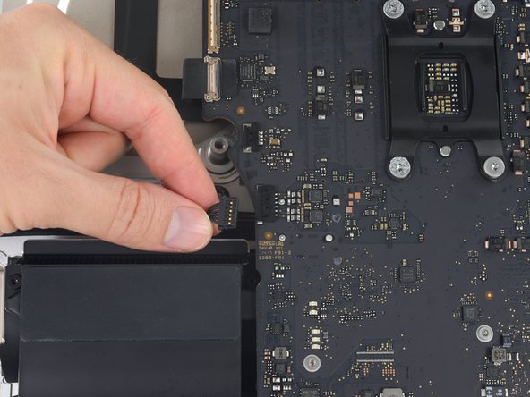
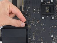
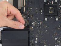
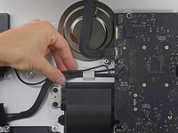
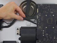
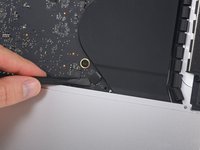
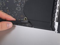
Tira suavemente del conector del cable del ventilador directamente desde su zócalo en la placa lógica.
-
-
-
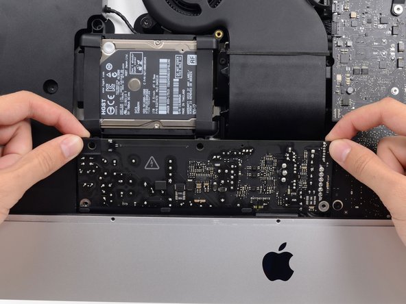
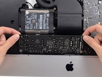
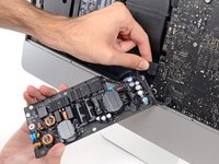
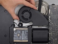
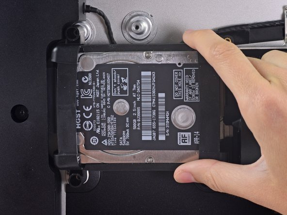
Levanta el disco duro desde el borde más cercano a la placa lógica y extraelo un poco del hueco.
-
-
-
Retira el tornillo Torx T8 de 7.3 mm que fija la bandeja del disco duro al gabinete trasero.
-
-
-
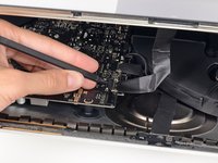
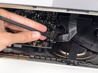
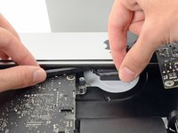
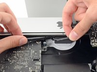
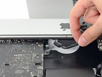
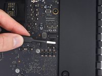
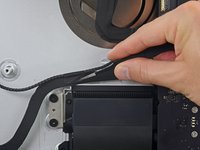
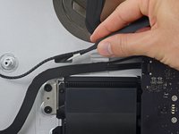
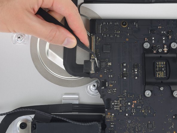
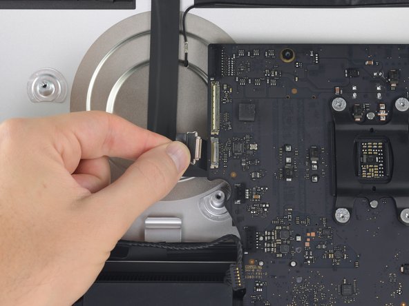
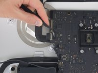
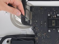
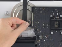
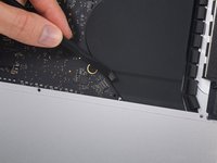
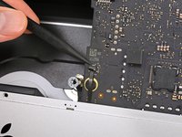
Tira suavemente del conector del cable del altavoz derecho hacia abajo y fuera de su zócalo en la placa lógica.
-
-
-
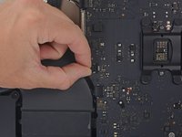
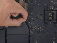
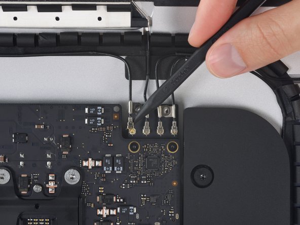
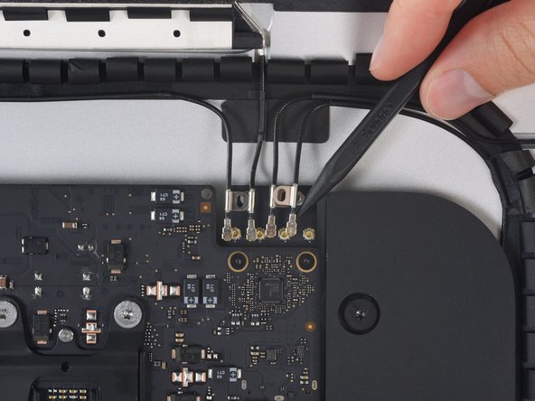
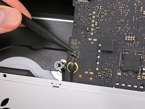
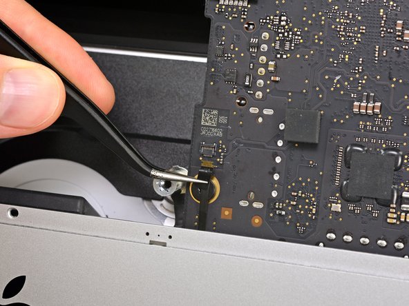
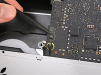
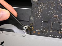
Gira el pestillo del conector ZIF del micrófono y extraiga el cable de su zócalo en la placa lógica.
-


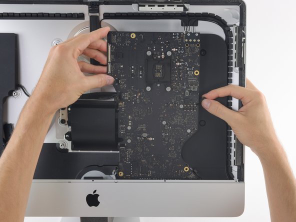


Para volver a armar tu dispositivo, sigue estas instrucciones en orden inverso.
Cancelar: No complete esta guía.
158 personas más completaron esta guía.
Un agradecimiento especial a estos traductores:
100%


Estos traductores nos están ayudando a reparar el mundo! ¿Quieres contribuir?
Empezar a traducir ›

80Guía Comentarios
An excellent guide - many thanks. The logic board was tricksy to get out - the card reader was jamming on the casing, but it came out with care. It's easy to trap the microphone cable and the power button cables when re-assembling, so they're worth looking out for. Successfully replaced the RAM and installed an SSD at the same time - many thanks.
Can a SSD or fusion drive be put in the place where the normal hard drive was?
An ssd can yes - that's what I did at the same time as upgrading the ram. As long as it's a 2.5" ssd it should be fine. The Samsung ssd I used was a but thinner than the hard drive that came out but that doesn't affect anything really. You'll need to either have a bootable clone of your drive, or install Sierra from a USB stick you've already prepared (which is what I did).
A Fusion drive is the terminology used by Apple when the use a board soldered 120ish Gb storage and a standard 1Tb 2.5 inch drive, and bind them together, if you throw in a 1Tb SSD in place of the existing standard hard drive you end up with 2 drives when you begin installation, you can find the instructions to merge the onboard and the new SSD back together again, and boy does it transform these machines, absolute pig with a factory fusion setup.
I also upgraded my hard-drive to a 512 GB Samsung SSD successfully along with installing the 32 GB of RAM. The guide was great, but I have a two comments.
1) The screws that hold the antenna connectors (Step 52) are were very tightly screwed into the board, and it is easy to strip the head of the screw. I stripped one of the screws… Luckily, it was easy to just pull up on the bluetooth/AirPort card and slide it out from its slot on the main board. Thus, an option to removing all the antenna wires, is to just pull the bluetooth/Airport card out. It was quite easy to slip back into the correct spot when reassembling as well.
2) It was only after I completed the repair that I realized that the top of the nice screwdriver provided in the repair kit contained more hidden bits!