Esta versión puede contener ediciones incorrectas. Cambie a la última instantánea verificada.
Qué necesitas
-
-
Use una moneda para girar el tornillo de bloqueo de la batería 90 grados en el sentido de las agujas del reloj.
-
-
-
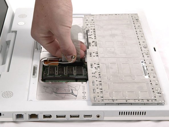
Tire de las pestañas de liberación del teclado hacia usted y levante el teclado hasta que se libere.
-
Da la vuelta al teclado, lejos de la pantalla, y recuéstelo boca abajo en el área del trackpad.
-
-
-
Utiliza un alfiler (o lo que quieras) para retirar las tres patas de goma de la carcasa inferior.
-
-
-
Hay una ranura en la pared del compartimento de la batería que bloquea la carcasa inferior en su lugar. Utiliza un destornillador plano pequeño para hacer palanca en el borde inferior de la ranura y tira hacia arriba de la carcasa inferior para liberar la ranura de las lengüetas que la sujetan.
-
-
-
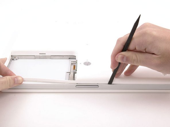
Pasa un spudger a lo largo de la costura entre la carcasa inferior y la carcasa superior en la parte frontal del ordenador para liberar las lengüetas que bloquean la carcasa inferior. Tira hacia arriba de la carcasa inferior y continúa utilizando el spudger según sea necesario hasta que oigas tres clics distintos.
-
-
-
-
Una vez que la parte frontal y los laterales de la carcasa inferior estén libres, gira el ordenador de modo que la parte posterior esté orientada hacia ti y tira de la carcasa inferior hacia arriba y hacia ti hasta que las pestañas posteriores salten (puede ser útil sacudir la carcasa hacia arriba y hacia abajo).
-
-
-
Retira los siguientes 10 tornillos del escudo inferior:
-
Seis Phillips de 3 mm
-
Tres Phillips de 7,5 mm
-
Uno Phillips de 14 mm
-
-
Este paso está sin traducir. Ayuda a traducirlo
-
Remove the following 11 screws from the bottom of the computer:
-
Three 3 mm Phillips around the battery compartment. (Some models may only have two screws.)
-
Three 4.5 mm Phillips along the optical drive bezel. (a magnetic screwdriver may help to lift these screws out)
-
One 11 mm Phillips in the lower right corner. (if present)
-
Four 14.5 mm Phillips.
-
-
Este paso está sin traducir. Ayuda a traducirlo
-
Turn over the computer and open it.
-
Remove the 2 Phillips screws (3mm) from the edges of the keyboard area.
-
Remove the 4 mm Phillips screw from the lower left corner.
-
-
Este paso está sin traducir. Ayuda a traducirlo
-
Lift the upper case and use a spudger or your finger to disconnect the trackpad connector hidden beneath the white plastic tab. Due to model variatons your trackpad connector may be different than the one pictured.
-
-
Este paso está sin traducir. Ayuda a traducirlo
-
Carefully lift the upper case about half of an inch and move it so that you can access the power and speaker cables.
-
-
Este paso está sin traducir. Ayuda a traducirlo
-
Lift the upper case enough to disconnect the blue and white power cable from the logic board. Using your fingernails or a dental pick, carefully pry the connector from its socket. Make sure you're pulling only on the connector and not on the socket.
-
-
Este paso está sin traducir. Ayuda a traducirlo
-
Carefully disconnect the multicolored speaker cable from the logic board. As before, make sure you're pulling only on the connector and not on the socket.
-
-
Este paso está sin traducir. Ayuda a traducirlo
-
Remove the following 16 screws:
-
Thirteen 3 mm Phillips.
-
One 3 mm Phillips. (actual screw not present in image)
-
Two 4 mm Phillips.
-
-
Este paso está sin traducir. Ayuda a traducirlo
-
Lift the top shield up from the right side, minding the upper left corner, which may catch on the metal framework.
-
If your iBook has Bluetooth, as discussed in the previous step, you will need to slide the antenna through the lower I-shaped hole in the shield before completely removing the shield.
-
-
Este paso está sin traducir. Ayuda a traducirlo
-
Remove the two Phillips screws at the corners of the modem.
-
-
Este paso está sin traducir. Ayuda a traducirlo
-
Disconnect the RJ-11 cable from the top of the modem.
-
-
Este paso está sin traducir. Ayuda a traducirlo
-
Turn the computer over and disconnect the fan cable from the logic board.
-
If present, remove the 4 Phillips screws securing the fan to the metal framework (one screw is hidden by the hand in the image) and lift the fan out of the computer. If no screws are present, continue on.
-
-
Este paso está sin traducir. Ayuda a traducirlo
-
Turn the computer over and remove the two Phillips screws from the white plastic fingers of the hinge grill.
-
-
Este paso está sin traducir. Ayuda a traducirlo
-
Remove the following 6 screws and 3 nuts from the heat sink:
-
One 2 mm Phillips extending from a finger on the left edge of the heatsink and adjacent the firewire port (not present on some models)
-
Three 3 mm Phillips from around the fan (some models may only have 2 screws).
-
One 3.5 mm Phillips on the left side of the heat sink (not present on some models).
-
One 4.5 mm Phillips at the top right corner of the heat sink.
-
One 6 mm Phillips at the lower left corner of the heat sink.
-
One 4 mm nut from the right side of the heat sink.
-
Two 4 mm screw nuts with attached springs from either side of the heat sink.
-
-
Este paso está sin traducir. Ayuda a traducirlo
-
Use a spudger to pry the heat sink up on the left side, near the hard drive.
-
-
Este paso está sin traducir. Ayuda a traducirlo
-
Grasp the heat sink in one hand and lift up the hinge grill in the other hand so that you can remove the heat sink from the computer.
-
-
Este paso está sin traducir. Ayuda a traducirlo
-
Remove the two Phillips screws securing the white plastic fingers of the I/O bezel to the metal framework.
-
-
Este paso está sin traducir. Ayuda a traducirlo
-
Lift up the left side of the computer and slide the I/O bezel away.
-
-
Este paso está sin traducir. Ayuda a traducirlo
-
Wedge a spudger between the RJ-11 board and the metal framework and slide the board to the left, off of the logic board.
-
-
Este paso está sin traducir. Ayuda a traducirlo
-
Disconnect the microphone cable at the front of the computer, between the left side of the hard drive and the metal framework.
-
-
Este paso está sin traducir. Ayuda a traducirlo
-
Use the black plastic loop to disconnect the display data cable from the logic board.
-
-
Este paso está sin traducir. Ayuda a traducirlo
-
Disconnect the orange optical drive ribbon from the logic board.
-
-
Este paso está sin traducir. Ayuda a traducirlo
-
1) With your fingernails, grasp the locking bar on either side and pull up a small amount (about 1/16" or 2 mm).
-
2) After disengaging the locking bar, slide the cable out of the connector.
-
-
Este paso está sin traducir. Ayuda a traducirlo
-
Release the optical drive ribbon clamp as described above. Slide the optical drive ribbon out of its connector.
-
-
Este paso está sin traducir. Ayuda a traducirlo
-
Tilt the computer up and disconnect the orange hard drive ribbon cable from the logic board.
-
-
Este paso está sin traducir. Ayuda a traducirlo
-
Remove the four Phillips screws securing the hard drive to the metal framework.
-
-
Este paso está sin traducir. Ayuda a traducirlo
-
Lift the hard drive up, carefully guiding the cable through the slot in the lower case.
-
-
Este paso está sin traducir. Ayuda a traducirlo
-
Remove the single Phillips screw securing the logic board to the metal framework.
-
-
Este paso está sin traducir. Ayuda a traducirlo
-
Close the display and flip the computer over.
-
Remove the following 8 screws:
-
Four 4 mm Phillips.
-
One 3.5 mm Phillips near the sleep light connector (may not be in your specific model).
-
One 3 mm Phillips with a large head in the lower left corner.
-
One wide 4 mm Phillips.
-
One 3 mm Phillips.
-
-
Este paso está sin traducir. Ayuda a traducirlo
-
Disconnect the inverter and sleep light cables from the logic board.
-
-
Este paso está sin traducir. Ayuda a traducirlo
-
Lift the logic board far enough to access and disconnect the battery connector.
-


Cancelar: No complete esta guía.
18 personas más completaron esta guía.
Documentos Adjuntos

2 comentarios
First of all, outstanding! I couldn't have done it otherwise. I especially liked the photography. I am a pro in that field and I know the good stuff when I see it.
I just have a few small suggestions.
1) You might want to warn about grounding for rank amateurs like me.
2) The screw sheets were fantastic but it might help to add the step/s involved. Also I found double sided foam tape was great for keeping the screws in place.
3) When removing the back cover I used kitchen matches camphored at one end as shims as I went along so I would not lose ground as I continued around the bottom cover. I also found a fifth of Jack Daniel's helped to steady my hands and give me patience.
4) The whole thermal compound thing was confusing. I looked up the suggested procedure and didn't know what to do about "the blue pads". I posted a question and got conflicting answers. It would be great if this could get resolved once and for all.
5) You might want to talk about installing the RAM when replacing the logic board
Thanks!