Saltar al contenido principal

Midframe Removal

Sólo Prerrequisito
Esta guía solo debería usarse como prerrequisito para otras guías. Por tanto, estará incompleta.

Qué necesitas

  1. Midframe Removal, Remove the front trim: paso 1, imagen 1 de 3 Midframe Removal, Remove the front trim: paso 1, imagen 2 de 3 Midframe Removal, Remove the front trim: paso 1, imagen 3 de 3
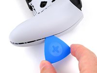
    • Place the controller on a work surface with the joysticks facing down.

    • Use a spudger or your finger to slide the Release tab to the left. The front trim should fall to the table.

    • If the front trim doesn't fall open, make sure the front trim has room to fall down and the Release tab is pushed all the way to the left.

    • Lift the controller up, leaving the front trim on the table.

    • During reassembly, insert the front trim at an angle so the top slots in first, then lower the trim into place and snap it onto the controller.

  2. Midframe Removal, Remove the joysticks: paso 2, imagen 1 de 3 Midframe Removal, Remove the joysticks: paso 2, imagen 2 de 3 Midframe Removal, Remove the joysticks: paso 2, imagen 3 de 3
    • Flip the controller over so the joysticks are facing up.

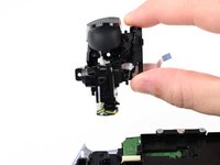
    • Lift the metal lever that holds the joystick in place until the joystick slides out slightly.

    • Slide the joystick out from its slot.

  3. Midframe Removal: paso 3, imagen 1 de 1
    • Repeat this process to remove the other joystick.

  4. Midframe Removal, Insert an opening pick: paso 4, imagen 1 de 3 Midframe Removal, Insert an opening pick: paso 4, imagen 2 de 3 Midframe Removal, Insert an opening pick: paso 4, imagen 3 de 3
    • The rear trim is held in place by fragile plastic clips. Work slowly and gently to avoid breaking the clips.

    • If you installed the back button paddles included with your controller, remove them before beginning this process.

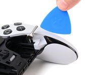
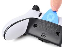
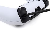
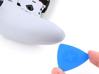
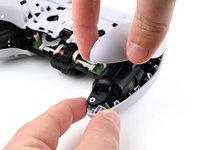
    • Insert the flat edge of an opening pick between the black portion of the rear trim and the top cover, near the joystick lever.

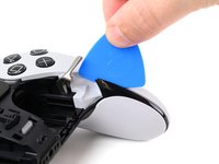
    • Slide the opening pick towards the bottom of the grip to release the clips.

  5. Midframe Removal, Release the clips: paso 5, imagen 1 de 2 Midframe Removal, Release the clips: paso 5, imagen 2 de 2
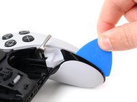
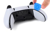
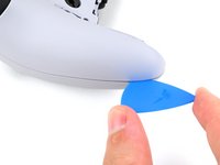
    • Slide the pick around to the rear of the controller and flip the controller over so the buttons are facing down.

    • Slide the opening pick around the edge of the rear trim to release the clips.

  6. Midframe Removal, Remove the rear trim: paso 6, imagen 1 de 3 Midframe Removal, Remove the rear trim: paso 6, imagen 2 de 3 Midframe Removal, Remove the rear trim: paso 6, imagen 3 de 3
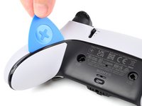
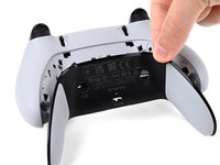
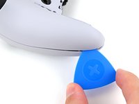
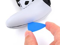
    • Slide the opening along the edge of the trim on the other grip.

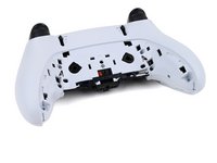
    • Once all clips are released, remove the trim.

    • If at any point the trim feels stuck, stop and look for any clips that may have re-engaged and release them with the opening pick to avoid damaging them.

  7. Midframe Removal, Remove the L1 and R1 buttons: paso 7, imagen 1 de 3 Midframe Removal, Remove the L1 and R1 buttons: paso 7, imagen 2 de 3 Midframe Removal, Remove the L1 and R1 buttons: paso 7, imagen 3 de 3
    • The L1 and R1 buttons are held in by two clips. If only one clip releases, move your spudger to the other side of the button to release the remaining clip. Don't continue prying on one side after a clip is released, or you risk breaking the other clip.

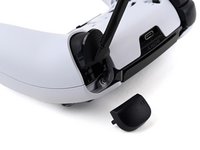
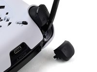
    • Insert the flat end of a spudger in the gap between the L1 and L2 buttons.

    • Use the spudger to pry out the L1 button.

    • The buttons tend to shoot out in this step. You can place your thumb over the button to prevent this.

    • Repeat this process to remove the R1 button.

  8. Midframe Removal, Remove the screws: paso 8, imagen 1 de 2 Midframe Removal, Remove the screws: paso 8, imagen 2 de 2
    • Remove the two 6.4 mm screws behind the L1 and R1 buttons.

    • Use a JIS J0 driver or an official iFixit Phillips PH0 driver, which is designed to be cross-compatible with JIS screws. Using a screwdriver other than an official iFixit driver or a JIS driver may result in stripped screws.

  9. Midframe Removal, Lift the release bar spring: paso 9, imagen 1 de 2 Midframe Removal, Lift the release bar spring: paso 9, imagen 2 de 2
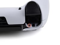
    • Rotate the controller so the grips are pointing towards you.

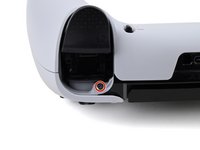
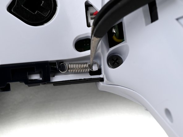
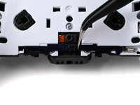
    • Use a pair of angled tweezers to lift the right end of the release bar spring off of the white post.

    • The spring is located below the RB button.

  10. Midframe Removal, Remove the trim release bar: paso 10, imagen 1 de 3 Midframe Removal, Remove the trim release bar: paso 10, imagen 2 de 3 Midframe Removal, Remove the trim release bar: paso 10, imagen 3 de 3
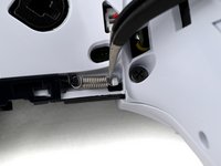
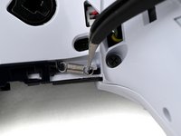
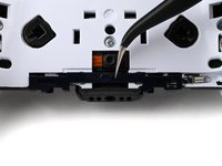
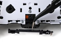
    • Use a pair of tweezers or your fingers to slide the release bar to the left.

    • Slide the release bar away from the controller to remove it.

  11. Midframe Removal, Remove the rear case screws: paso 11, imagen 1 de 1
    • Remove the nine screws securing the rear case:

    • Seven 6.4 mm‑long screws

    • Two 10.5 mm‑long screws

  12. Midframe Removal, Insert an opening pick: paso 12, imagen 1 de 2 Midframe Removal, Insert an opening pick: paso 12, imagen 2 de 2
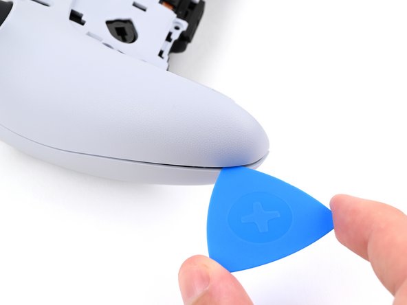
    • Insert the point an opening pick in the gap along the outside edge of one of the controller grips, near the bottom.

  13. Midframe Removal, Separate the rear case: paso 13, imagen 1 de 3 Midframe Removal, Separate the rear case: paso 13, imagen 2 de 3 Midframe Removal, Separate the rear case: paso 13, imagen 3 de 3
    • Pry with the opening pick to separate the rear case from the front case by releasing the clips that hold them together.

    • Continue prying along the edge of the controller until one side is separated.

  14. Midframe Removal: paso 14, imagen 1 de 2 Midframe Removal: paso 14, imagen 2 de 2
    • Repeat this process to separate the other side of the rear case.

  15. Midframe Removal, Remove the rear case: paso 15, imagen 1 de 3 Midframe Removal, Remove the rear case: paso 15, imagen 2 de 3 Midframe Removal, Remove the rear case: paso 15, imagen 3 de 3
    • If at any point the case feels stuck, stop and look for any clips that may have re-engaged and release them with the opening pick to avoid damaging them.

    • Hold the main body of the controller with one hand.

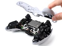
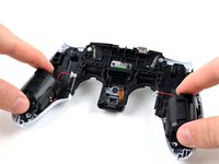
    • Lift the rear case with your other hand. It should lift at an angle.

    • Pushing slightly towards the L and R buttons, lift the rear case off of the controller and remove it.

    • During reassembly, make sure the plastic covers for the adaptive trigger assembly adjustment sliders are correctly installed over the sliders.

  16. Midframe Removal, Replace the slider covers: paso 16, imagen 1 de 3 Midframe Removal, Replace the slider covers: paso 16, imagen 2 de 3 Midframe Removal, Replace the slider covers: paso 16, imagen 3 de 3
    • The rear case holds two small plastic covers for the adaptive trigger assembly adjustment sliders. These may have come off during removal. Place them back in the rear cover now to avoid losing them.

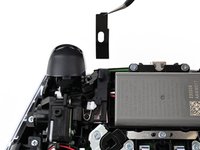
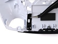
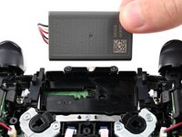
    • Use a pair of tweezers or your fingers to lift the cover from the controller.

    • Slide the flat end of the cover under the plastic tab in the rear case.

    • Make sure it is placed so it can move freely in its groove. The edge with the notch should be towards the middle of the controller.

    • If a cover got bent during the rear case removal or reassembly process, apply a small amount of heat with a hair dryer to restore it to its original shape.

    • During reassembly, you can use a small piece of painter's tape on the outside of the rear case to hold the covers in place.

  17. Midframe Removal, Lift the battery: paso 17, imagen 1 de 2 Midframe Removal, Lift the battery: paso 17, imagen 2 de 2
    • If your battery is swollen or deformed in any way, take appropriate precautions.

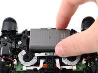
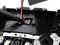
    • Lift the battery and move it to the right, so the connector underneath the battery is accessible.

  18. Midframe Removal, Disconnect the battery: paso 18, imagen 1 de 3 Midframe Removal, Disconnect the battery: paso 18, imagen 2 de 3 Midframe Removal, Disconnect the battery: paso 18, imagen 3 de 3
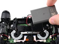
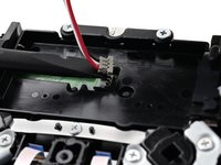
    • Use the flat end of a spudger to pry up the low profile connector.

    • Only pry on the connector. Do not pry on the wires, as that may damage the wires.

    • Remove the battery.

  19. Midframe Removal, Move the vibration motor cable: paso 19, imagen 1 de 3 Midframe Removal, Move the vibration motor cable: paso 19, imagen 2 de 3 Midframe Removal, Move the vibration motor cable: paso 19, imagen 3 de 3
    • This procedure is written using the R2 trigger assembly, which is on your left. The procedure to remove the L2 assembly is identical.

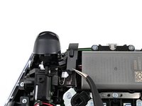
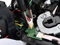
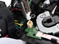
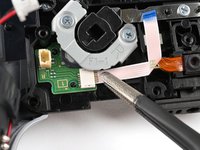
    • Use a pair of tweezers to disconnect the vibration motor cable by lifting the JST connector out of its socket.

    • This cable is connected to the back button board, between the RB or LB button and the vibration motor.

    • Continue lifting until the vibration motor cable is free of the clip on the trigger assembly.

  20. Midframe Removal, Remove the trigger assembly screws: paso 20, imagen 1 de 1
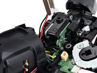
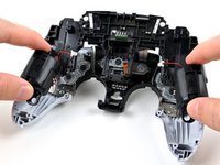
    • Remove the two 6.4 mm‑long screws securing the trigger assembly.

  21. Midframe Removal, Lift the trigger assembly: paso 21, imagen 1 de 2 Midframe Removal, Lift the trigger assembly: paso 21, imagen 2 de 2
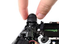
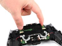
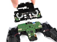
    • Lift the trigger assembly away from the controller and hold it so you can access the ribbon cable underneath it.

    • Do not try to fully remove the trigger assembly yet. It's still connected by a ribbon cable, which you'll disconnect in the next step

  22. Midframe Removal, Disconnect the trigger assembly: paso 22, imagen 1 de 3 Midframe Removal, Disconnect the trigger assembly: paso 22, imagen 2 de 3 Midframe Removal, Disconnect the trigger assembly: paso 22, imagen 3 de 3
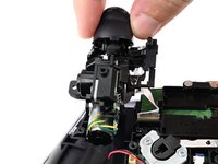
    • While holding the trigger assembly above the controller, use a pair of tweezers to disconnect the trigger assembly ribbon cable by gripping the pull tab and pulling away from the connector.

    • Remove the trigger assembly

  23. Midframe Removal, Remove the R back button ribbon cable: paso 23, imagen 1 de 2 Midframe Removal, Remove the R back button ribbon cable: paso 23, imagen 2 de 2
    • Make sure you removed both the L2 and the R2 adaptive trigger assemblies before continuing.

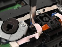
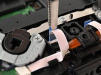
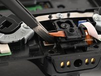
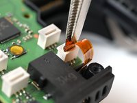
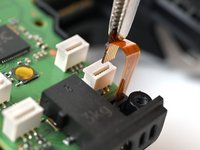
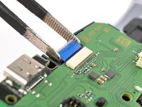
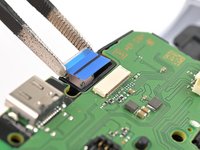
    • Use a pair of tweezers to disconnect the RB back button ribbon cable connector from the motherboard by griping the blue tab on the ribbon cable and pulling away from the connector.

    • The RB back button has an "R" engraved on the bracket and it's to your left.

  24. Midframe Removal: paso 24, imagen 1 de 2 Midframe Removal: paso 24, imagen 2 de 2
    • Use a pair of tweezers to move the RB back button ribbon cable out from its plastic clip.

  25. Midframe Removal: paso 25, imagen 1 de 2 Midframe Removal: paso 25, imagen 2 de 2
    • Use a pair of tweezers to disconnect the RB back button ribbon cable from the back button board.

  26. Midframe Removal, Remove the rear microphone: paso 26, imagen 1 de 2 Midframe Removal, Remove the rear microphone: paso 26, imagen 2 de 2
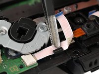
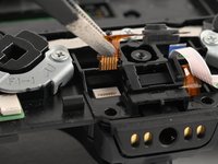
    • Use a pair of tweezers to disconnect the rear microphone ribbon cable from the motherboard.

    • Continue lifting to remove the microphone.

    • During reassembly, make sure to slot the plastic on the right edge of the microphone into the bracket on the microphone housing.

  27. Midframe Removal, Disconnect the L back button: paso 27, imagen 1 de 2 Midframe Removal, Disconnect the L back button: paso 27, imagen 2 de 2
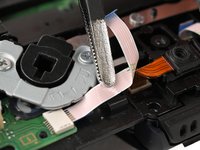
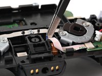
    • Use a pair of tweezers to disconnect the LB back button ribbon cable from the motherboard by gripping the blue tab and pulling away from the connector.

  28. Midframe Removal, Remove the battery bracket screws: paso 28, imagen 1 de 1
    • Remove the three screws securing the battery bracket:

    • Two 6.4 mm‑long screws near the middle of the left and right edges of the battery bracket

    • One 10.4 mm‑long screw near the center of the battery bracket

  29. Midframe Removal, Remove the battery bracket: paso 29, imagen 1 de 2 Midframe Removal, Remove the battery bracket: paso 29, imagen 2 de 2
    • Lift and remove the battery bracket.

  30. Midframe Removal, Disconnect the front microphone ribbon cable: paso 30, imagen 1 de 2 Midframe Removal, Disconnect the front microphone ribbon cable: paso 30, imagen 2 de 2
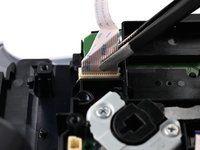
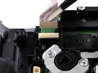
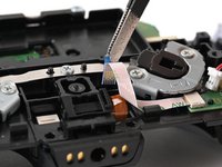
    • Use a pair of tweezers to disconnect the front microphone ribbon cable from the motherboard by gripping the blue pull tab and pulling away from the connector.

    • The front microphone connector is below LB back button connector, at the bottom of the motherboard.

  31. Midframe Removal, Disconnect the touchpad ribbon cable: paso 31, imagen 1 de 2 Midframe Removal, Disconnect the touchpad ribbon cable: paso 31, imagen 2 de 2
    • Use a pair of tweezers to disconnect the touchpad ribbon cable from the motherboard by gripping the blue pull tab and pulling away from the connector.

    • This connector can be difficult to disconnect. If you grip the pull tab by the sides, as shown in the picture, squeeze just hard enough to grip the tab to avoid bending the tab and ribbon cable.

  32. Midframe Removal, Remove the motherboard: paso 32, imagen 1 de 2 Midframe Removal, Remove the motherboard: paso 32, imagen 2 de 2
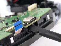
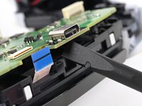
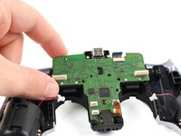
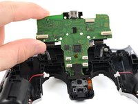
    • Insert the flat end of a spudger underneath the motherboard, below the USB-C port.

    • Use the spudger to lift the motherboard free of the small clips that secure it.

  33. Midframe Removal: paso 33, imagen 1 de 2 Midframe Removal: paso 33, imagen 2 de 2
  34. Midframe Removal, Remove the speaker: paso 34, imagen 1 de 2 Midframe Removal, Remove the speaker: paso 34, imagen 2 de 2
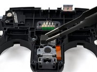
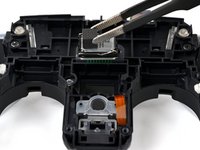
    • Use tweezers or your fingers to lift and remove the speaker from the center of the midframe.

    • During reassembly:

    • Check that your new speaker has a piece of foam on the back. If it doesn't, transfer the foam from the old speaker to the new one.

    • Install the speaker so the raised portion of the contact springs are to the right. If you are unsure of the correct orientation, check the motherboard and make sure the springs make contact with the posts on the motherboard.

  35. Midframe Removal, Remove the midframe: paso 35, imagen 1 de 1
    • Remove the five screws securing the midframe:

    • Three 6.4 mm‑long screws

    • Two 10.4 mm‑long screws

  36. Midframe Removal: paso 36, imagen 1 de 2 Midframe Removal: paso 36, imagen 2 de 2
    • Grab the vibration motor housings and lift the midframe to remove it.

    • Make sure the touchpad cable slides freely through the opening in the midframe.

Conclusión

To reassemble your device, follow these instructions in reverse order.

Spencer Pennington

Miembro Desde 09/09/23

16,989 Reputación

113 Guías creadas

Equipo

iFixit Miembro de iFixit

Staff

118 Miembros

19,446 Guías creadas

0 comentarios

Agregar Comentario

Ver Estadísticas:

Ultimas 24 horas: 0

Ultimos 7 días: 0

Ultimos 30 días: 0

Todo El Tiempo: 18