Esta versión puede contener ediciones incorrectas. Cambie a la última instantánea verificada.
Introducción
Esta guía te da un vistazo a los componentes principales del Fujifilm X100T, incluyendo los lentes y la tarjeta madre, y provee instrucciones completas de desarmado.
Qué necesitas
-
-
Desliza la pequeña pestaña negra en el inferior de la cámara hacia la izquierda para desbloquear la cubierta de la batería.
-
-
-
Empezando en una de las esquinas, usa una espátula para hacer palanca en la cubierta de piel de la cámara.
-
-
Este paso está sin traducir. Ayuda a traducirlo
-
This is a camera produced by a Japanese camera manufacturer. The Japanese camera industry loves using JIS (Japanese Industrial Standard) screws.
-
Don't be tempted by your Phillips screw driver collection. Although PH#00 will interchange with JIS#00, it is not a perfect fit. Using Phillips will cause more wear on the head of the JIS screws and cause the screws to prematurely strip.
-
Have both JIS#00 and JIS#000 screw drivers available for this teardown. Luckily, both bits are included in the ifixit 64bit kit.
-
-
Este paso está sin traducir. Ayuda a traducirlo
-
Remove the bottom plate and the tripod mount by lifting them using your hands.
-
The tripod mount is keyed and fits into a series of pegs on the back side of the bottom plate.
-
-
Este paso está sin traducir. Ayuda a traducirlo
-
Get your picks ready!
-
To get any deeper into this camera, the right-hand port cover assembly must be removed first. Once this is removed, you will have access to the screws that secure the other components.
-
There's a tiny hole toward the bottom right of the battery compartment. Using the pick tool, press into that hole.
-
A plastic rod will release. That plastic rod is the axis the hinge rotates about.
-
-
Este paso está sin traducir. Ayuda a traducirlo
-
Fuji! What did we tell you about hiding screws behind closed doors! That's pretty under the table Fuji. Don't do it again. Promise?
-
The devil's in the details with this camera. Slide the port cover off the hinge rod.
-
Using a pair of pliers, pull the rod out of the top plate of the camera. Now you'll finally have access to all the screws that need to be removed.
-
-
Este paso está sin traducir. Ayuda a traducirlo
-
Remove the three 5.0 mm screws by the micro-USB, micro-HDMI and remote ports.
-
Remove the screw hidden behind the port cover hinge.
-
The port cover assembly should come off with ease. If it is stuck, try prying with plastic shims.
-
-
Este paso está sin traducir. Ayuda a traducirlo
-
Remove the two 6.0 mm screws beneath the port cover assembly.
-
-
Este paso está sin traducir. Ayuda a traducirlo
-
Remove the four 5.0 mm screws on the side of the camera that is opposite to the battery.
-
-
Este paso está sin traducir. Ayuda a traducirlo
-
Remove the two 2.5 mm screws on the bottom face of the camera.
-
-
Este paso está sin traducir. Ayuda a traducirlo
-
Once the electronics are exposed, it is highly recommended that you remain ESD safe. ESD can fry your precious electronics, and pass thousands of volts through components only rated for a few V DC. ESD can sure ruin your day if you are not careful.
-
Use an ESD mat and wrist strap, and make sure you are grounded for the remaining of the teardown. Make sure your ESD mat is connected to the ground of a nearby outlet, and make sure your house actually has a ground. Consult an electrician if you are unsure.
-
-
Este paso está sin traducir. Ayuda a traducirlo
-
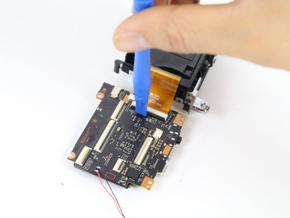
Remove the orange ribbon cable by opening up the ZIF connector with a plastic prying tool or toothpick.
-
-
-
Este paso está sin traducir. Ayuda a traducirlo
-
Remove the white/blue ribbon cable from the motherboard by gently pulling with your hands.
-
-
Este paso está sin traducir. Ayuda a traducirlo
-
Remove the 2.5 mm screw in the center, above the removed LCD screen.
-
Remove the two 4.0 mm screws on the right.
-
-
Este paso está sin traducir. Ayuda a traducirlo
-
Remove the two 4.5 mm screws on the side of the camera opposite of the battery.
-
-
Este paso está sin traducir. Ayuda a traducirlo
-
Peel off the copper tape connecting the frame to the camera.
-
-
Este paso está sin traducir. Ayuda a traducirlo
-
Remove the adhesive tape holding the speaker.
-
The speaker is held into place by double sided tape. Pull it off the steel frame and move it toward the bottom of the camera
-
-
Este paso está sin traducir. Ayuda a traducirlo
-
Remove these two ribbon cables so they don't get cut or damaged when removing the entire steel frame.
-
-
Este paso está sin traducir. Ayuda a traducirlo
-
Fold back the steel frame by lifting it off and gently pulling it to the side using your hand.
-
Remove the three 4.2 mm screws on the green chip.
-
-
Este paso está sin traducir. Ayuda a traducirlo
-
Locate the orange ribbon cable on the side of the camera that has the battery slot.
-
Remove the ribbon cable from the ZIF socket using a plastic opening tool.
-
Remove the ribbon by lifting it off with your hands.
-
-
Este paso está sin traducir. Ayuda a traducirlo
-
Remove the rubber eyepiece guard by lifting it off with your hands.
-
If the rubber eyepiece is being stubborn, an old giftcard won't mind :D
-
-
Este paso está sin traducir. Ayuda a traducirlo
-
Remove the two 4.0 mm screws from the front of the camera. These are most likely T1 torx screws.
-
I can't stress enough how tiny these screws are. Pencil point sized.
-
The closest bit in the ifixit kit is the star shaped #2 screw head.
-
-
Este paso está sin traducir. Ayuda a traducirlo
-
Remove the top frame by lifting it off and pulling it towards the backside of the camera.
-
-
Este paso está sin traducir. Ayuda a traducirlo
-
Use a plastic opening tool to detach the two ribbon cables from the top frame.
-
-
Este paso está sin traducir. Ayuda a traducirlo
-
Locate the adhesive connecting the black and red wires above the green board.
-
Remove the adhesive by gently pulling it off with your hand.
-
Remove the copper tape that grounds the sensor heatsink to the sensor PCB.
-
-
Este paso está sin traducir. Ayuda a traducirlo
-
Use a plastic opening tool to pry off the ribbon located next to the top-right of the green sensor board.
-
-
Este paso está sin traducir. Ayuda a traducirlo
-
Use a plastic opening tool and metal tweezers to lift up the ribbon located next to the center-right section of the green board.
-
Remove the CMOS sensor aluminum heatsink by lifting it up with your hands. The sensor, PCB and heatsink are integrated into one unit.
-
-
Este paso está sin traducir. Ayuda a traducirlo
-
You should be wearing nitrile gloves when working with lens assemblies. Oils from fingerprints leave marks on the lens elements and cause major headaches during reassembly.
-
Remove the four 3.2 mm screws on the silver lens cover.
-
-
Este paso está sin traducir. Ayuda a traducirlo
-
Use a plastic opening tool to lift up the silver lens cover.
-
-
Este paso está sin traducir. Ayuda a traducirlo
-
Remove the three 3.5 mm screws on the black lens cover.
-
-
Este paso está sin traducir. Ayuda a traducirlo
-
Remove the three 3.5 mm screws on the spring-loaded cover.
-
-
Este paso está sin traducir. Ayuda a traducirlo
-
Remove the spring and the lens by gently lifting both the components upwards.
-
-
-
Una vez que los lentes se hayan retirado, voltea la cámara y desatornilla los dos tornillos de 4.0 mm en el frente de la cámara, a lado de la cubierta de los lentes.
-
-
-
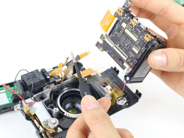
Usando pinzas de precisión, remueve la cinta blanca de la esquina de la tarjeta amdre.
-
Retira los dos tornillos de 4.0 mm del lado superior izquierdo e inferior izquierdo.
-
Después del retiro de los tornillos, con cuidado separa la tarjeta madre de la cubierta de la batería separando las dos partes.
-


Para reensamblar tu dispositivo, sigue estas instrucciones en orden inverso.
Para reensamblar tu dispositivo, sigue estas instrucciones en orden inverso.
Cancelar: No complete esta guía.
20 personas más completaron esta guía.
Un agradecimiento especial a estos traductores:
100%

¡ Fernando Salazar Garcia nos está ayudando a reparar el mundo! ¿Quieres contribuir?
Empezar a traducir ›
Equipo

Cal Poly, Team 70-1, Forte Winter 2016 Miembro de Cal Poly, Team 70-1, Forte Winter 2016
CPSU-FORTE-W16S70G1
4 Miembros
5 Guías creadas
27 comentarios
Thanks for great guide. 1 little question. I have dust on the front cover of viewfinder. Can I just take the top cover (step 19,20) without disassembling other parts in previous steps?
Thank you in advance
+1
i would like to see top cover disassembled too - same issue, dust in viewfinder
That should be possible! Based on posted pictures it seems to me that top plate is being hold in place by 5 points. Two of them are easily accessible from the front (step 19) but other 3 are hidden and may require partial disassembly to get proper access. There is one screw on each side of a camera (step 9 on top and step 14 n top) but most difficult is the one hidden behind back panel (step 13 red circle) to get there may really require taking the whole back of the camera off. Unless You are skilled with some level of previous experience .... I would let the technician to clean the dust out.