
Following up from iFixit's current connector overview "Reconocimiento y desconexión de conectores de cable", a full connector categorisation structure seemed like a logical next step.
Beginning with a general overview, and then looking at each category to understand the differences and ways of operating them, this wiki should give some useful insights for anyone uncertain about the operation of connectors in repair.
This basic overview shows how we've categorised the connectors in this list.

FPC/FFC
FPCs (Flexible Printed Circuits) or FFCs (Flexible Flat Cables) are a very common type of cable used to connect components together within electronics. Often referred to as ribbon cables, these flat cables are malleable and very low profile, making them suitable for compact mobile devices and specialist hardware alike.
The connectors which link an FPC or FFC to a PCB (Printed Circuit Board) can vary widely by application, and the types each have different benefits, drawbacks, and methods of operation.
FPC/FFC: ZIF
ZIF (Zero-Insertion-Force) connectors may be the most common, and most varied of the connectors in this list. They are easy to insert, and often have a locking mechanism which holds the FPC/FFC in place. The retention method is important to identify before operating a ZIF, as mistaking one for another can cause damage to these small and fragile connectors.
Front-Flip/Flip-Lock
This type of ZIF connector has a small lever pointing in the direction of the FPC/FFC. The ZIF can be inserted while the lever is in the upright position, and is locked in place when the lever is 'flat', in parallel to the PCB. A spudger or a fingernail can be used to open this lever and unlock the connector, after which the FPC can easily be pulled horizontally out of the housing.
Shown: Reconocimiento y desconexión de conectores de cable
 |  |
Back-Flip
Back-flip connectors operate very similary to front-flip, however their locking lever is reversed, facing away from the insertion side of the FPC. Both are very common, and oberservation and careful trial and error may be needed to distinguish which one you are dealing with.
Shown: Kobo Clara Colour (N367B) Motherboard Replacement
 |  |
Push-Lock
A less common, but still considerable retention method uses barbed teeth inside the connector that allows for latch-free insertion, but for which pushing a release button or bar is necessary.
It is important not to pull an FPC out of a connector until you are sure that there is no retention method that you've missed.
Shown: Reemplazo de la placa LED de la PlayStation 5
 |  |
Pinch-Lock
An even rarer version of this is a pinch-style locking mechanism, where the barbed teeth are released by squeezing the connector together to unlock the FPC.
Shown: Reemplazo de la placa madre y el disipador de calor
 |  |
Locking-Bar
Some ZIF connectors use a locking latch which flaps down over the connector for a rigid and secure mount once the FPC is inserted. These can be tricky to flip up, but using a pick or spudger under the bar that wraps around the outside seems to be the most effective method.
The example shows a wire bundle instead of an FPC, but the same procedure applies.
Shown: IPEX Cabline CA
 |  |
Locking-Cage
Similar to the Locking-Bar, but with a full cover over the top for increased rigidity and dust ingress prevention, the locking cage functions very similarly.
The example shows a wire bundle instead of an FPC, but the same procedure applies.
Shown: IPEX Cablin CA II
 |  |
Slide-Lock
Slide-locks use a sliding (often plastic) latch to hold the FPC in place. They often have arrows indicating which direction to slide the latch, and once this has been done, the FPC should pull free with ease. These often have a plastic pull tab to assist with FPC removal.
Shown: Reemplazo de la placa de audio de Steam Deck
 |  |
Non-Locking
Some ZIF connectors do not have any notable locking method other than a tight friction fit, and these can be inserted and removed with only the application of minimal force. They often have a plastic tab close to the end of the FPC to accomodate the user to pull the connector directly out, however this is not the only type of ZIF connector which can have this feature, so it is important to always identify what sort of connector is being used before assuming that it is non-locking.
Shown: Reemplazo de la placa LED de la PlayStation 5
 |  |
Other
There are various other ZIF connector retention styles, many of which are proprietary or uncommon. If you can, find instructions that match the device, and otherwise proceed with caution.
FPC/FFC: Press-Fit
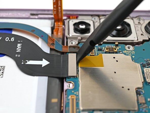
Press-fit connectors are among the most popular connectors in mobile devices, and with good reason: they are low-profile, high-density, and easy to operate. To remove a press-connector simply get underneatgh the flat top with a spudger or fingernail, and pry it upwards gently. To reinstall, align the pins and press down slightly until there is a tactile click.
Many sizes exist of these, with small ones being used for peripheral connections such as fingerprint sensors, batteries and speakers. Larger ones are often used for display connections, cameras, and mother-daughterboard interconnects.
Shown: Sustitución de la placa madre del Samsung Galaxy S23 Plus
 |  |
Mezzanine
Mezzanine types are fundamental connectors as they link primary functions such as power and data within sub-assemblies of devices. They come in many forms, with many leveraging the above ZIF connectors in compact consumer electronics. In specialised applications, there are other unique mezzanine connectors suited to specific use-cases.
High-Speed Data
High-speed data-focussed mezzanine connectors often use a lot of pins in an array, and may also use alignment pillars and locking mechanisms. They focus on signal strength and integrity, and it's important to be careful around the (often fragile) pins that they use.
Shown: Reemplazo de la tarjeta gráfica de Mac Pro a finales de 2013 / Molex HD Mezz Connector
 |  |
High-Power
Specialised high-power mezzanine interfaces often use thick-gauge wire and large contact pads to sustain high currents. They often use alignment pins and a strong locking function such as tabs, latches or even screws in some cases.
Shown: Desmontaje de Mac Pro 2009-2012 / Molex EXTreme Guardian Connector
 |  |
Edge / Compression
Edge connectors are unique due to their integration as physical parts of the PCBs that they are connecting. These use conductive pads in combination with sprung compression interfaces to ensure reliable contact. This is what many of the aforementioned high-power mezzanine connectors use as well, as they need maximum contact for high currents.
Not all use-cases are so specialised however, and the following spring connectors are used in some of the most common interfaces in electronics.
Spring Fingers
Spring fingers are essentially just springs that act as contacts between conductive pads on the docking PCB, and connect to traces on the receiving PCB, allowing for electrical connection without using a cable.
Examples within electronics include expandable memory, storage and networking using the M.2 standard, DIMM and CAMM2 standards as well as the PCIe expansion interface. Additionally, many IO (input/output) ports also use this technology, including USB and HDMI. Power plugs in most regions also rely on a scaled-up version of spring fingers to ensure a friction-fit and good electrical contact.
Shown: Memory in Sustitución de la memoria LPCAMM2 del Lenovo ThinkPad T14 Gen 7 / USB Port in Sustitución del puerto USB-C del Lenovo ThinkPad T14 Gen 7
 |  |
 |  |
Pogo-Pins
Pogo pins are generally larger than spring fingers, and are suitable for external use in consumer electronics. They are often known for their use as the interface for removable batteries in older phones, but are vital to modern wearables as well. The example of a pogo-pin-based charging interface for wireless earbuds is given.
This sort of connector is ideal for expansion or no-fuss contact charging in low-power applications. Users generally are not fully aware that they are operating an electronic connector, and repairs on devices that apply these connectors are simple (unless the compression connector itself is broken).
Shown: Pogo-Pin charging Interface on the Desmontaje de Nothing Ear (1)
 |  |
Zebra/Elastomeric
Zebra connectors are also a type of compression connector, as they sit in between two sets of conductive pads. They are unique because they are striped, alternating between traces, allowing for higher bandwidth than with traditional compression connectors. This allows them to send basic data, not only power, making them capable of sending signals to LCD displays mounted on PCBs amongst other, more specialised applications.
Shown: LCD Zebra Connector
 |  |
RF/Coaxial
Snap-On Coax
One of the most common yet most fiddly connectors on this list are snap-on coaxial connectors. These are tiny and can be difficult to align, especially in tight spaces within compact consumer electronics, which is where they are often used.
To uninstall a micro-coax connector, lever the head up gently from below with precision tweezers or a spudger, similarly to a press-connector.
Reinstallation is more tricky, and precise alignment is vital. One common approach is to hold the round plug head with a set of precision tweezers, and once it is aligned over the socket pin, press down with a spudger or fingernail.
Shown: Sustitución del puerto de carga USB-C y la placa de carga del Samsung Galaxy S20 FE 5G
 |  |
Other Coax
Not all radio frequency connectors use the round-headed snap-on interface, some now use conventional FPC/FFCs alongside ZIF or press-fit connectors.
Wire to Board
Within devices, FPCs are becoming more and more common, but conventional wires (or wire bundles) are still used often, and have their own range of connector types.
Headers
Headers consist of an array of pins, usually in a rectangular layout, while the plug consists of an array of holes which fit onto the pins, and are kept in place simply using friction. There is typically no retention method on these connectors, and a small tug will easily unplug them. Headers are most frequently vertically oriented, but in some cases, headers may lie horizontally on a PCB, especially on an edge or in a tight space.
Simple headers are also used for internal USB expansion in desktop computers, and are popular on micro-processors such as Arduino and Raspberry Pi.
 |  |
Box-Headers
While friction between the pins and plug is usually the primary retention method in conventional headers, Box-Headers use an additional box around the pins to ensure a more robust mate. These connectors often also use a small retention tab or rail to ensure alignment and to prevent accidental removal. These connectors do not typically have a locking mechanism, and it is safe to pull them out with a small application of force.
 |  |
 |  |
JST
These typically white connectors are incredibly popular, and found in most electronic devices. They come in both simple header and box-header types, and with various pin counts and sizes. Some versions also use locks to prevent accidental disconnection.
These are not necessarily a seperate category from the previous two, but overlap them, and their popularity merits an honourable mention.
 |  |
 |  |
Locking Connectors
Some header-adjacent connectors use locking mechanisms. An example is SATA, which uses a box-header, but with edge-style-contacts on a 'blade' rather than a simple array of pins. SATA is a standard internal data-transfer cable, and uses a metal locking tab to keep it in place. Squeezing the locking tab before pulling the plug out of the header is necessary to remove it. It is common for internal wire-to-board connectors to have locking mechanisms to prevent dislodgement during transport or prolonged use, and they exist in various formats.
 |  |
Power Cable Connectors
Power cables often require bundles of cables to safely conduct electricity in a less fragile form-factor than FPCs can accomodate. Therefore, the connectors also need to be more robust; The connectors of power cables are often a combination between a reinforced box-header and a secure locking mechanism. The most prevalent models are Molex's mini-fit series, which are used in various proprietary devices, and in desktop PCs in accordance with the ATX standard.
These use a simple rocking lock tab on the outside of the connector in combination with deep-set pins which use friction to remain aligned. Some may require quite a lot of force to remove, due to the amount of friction between the plug and receptacle. Always ensure that the lock is disengaged before attempting to remove these connectors to prevent damage.
 |  |
Sliding Headers
When headers lie flat on a PCB, they may use a single row of pins to fit within a lower-profile constraint. The below image shows a flat-format header with a horizontal mate. This is ultimately still a header, but one that is slightly more tricky to operate due to its orientation. Using a spudger to gently slide the connector out of its housing, possibly alternating side to side to wiggle it out gently, these connectors can be a bit of a hassle, but are relatively robust and predictable.
Reconocimiento y desconexión de conectores de cable
 |  |
Molex Pico-EZmate
These tiny, fragile connectors look similar to a conventional header, except that the plug must be removed vertically, and at a small angle. These use contacts that are more similar to edge connectors than to simple pin-interface headers, and are most commonly found as fan connectors in compact devices, taking the place of larger JST-style headers.
These are extremely fragile and the utmost care must be taken to prevent damage.
[Molex Pico-EZmate from https://www.ifixit.com/Guide/Mac+mini+(2...]
 |  |
Please comment or suggest an edit if you know of a board-to-board connector that is not listed.

0 comentarios