Saltar al contenido principal

Esta versión puede contener ediciones incorrectas. Cambie a la última instantánea verificada.

Qué necesitas

  1. , Bateria: paso 1, imagen 1 de 1
    • Use una moneda para girar el tornillo de bloqueo de la batería 90 grados en el sentido de las agujas del reloj.

  2. : paso 2, imagen 1 de 1
    • Levante la bateria de la computadora.

  3. , Teclado: paso 3, imagen 1 de 1
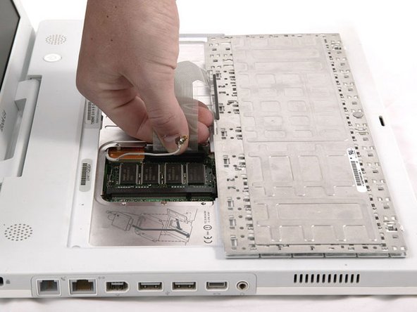
    • Tire de las pestañas de liberación del teclado hacia usted y levante el teclado hasta que se libere.

    • Si el teclado no se suelta, use un destornillador plano pequeño para girar el tornillo de bloqueo del teclado 180 grados en cualquier dirección y vuelva a intentarlo.

    • Da la vuelta al teclado, lejos de la pantalla, y recuéstelo boca abajo en el área del trackpad.

  4. : paso 4, imagen 1 de 1
    • Si la computadora tiene una tarjeta AirPort instalada, siga los siguientes tres pasos para eliminarla.

    • Empuje el broche de alambre lejos de la tarjeta AirPort y hacia la pantalla, luego gire hacia arriba para liberarlo de la protección de RAM.

  5. : paso 5, imagen 1 de 1
    • Sujete la lengüeta de plástico transparente en la tarjeta AirPort y tire hacia la pantalla.

  6. : paso 6, imagen 1 de 1
    • Sostenga la tarjeta AirPort con una mano y use su otra mano para quitar el cable de la antena.

  7. : paso 7, imagen 1 de 1
    • Retire los cuatro tornillos plateados Phillips que aseguran el protector de RAM.

  8. : paso 8, imagen 1 de 1
    • Sujete el soporte de metal en la parte superior del protector de RAM y tire hacia arriba para quitar el protector.

  9. : paso 9, imagen 1 de 1
    • Tire del cable del teclado hacia arriba desde la placa lógica, sosteniendo el cable lo más cerca posible del conector.

    • Asegúrese de volver a conectar el cable del teclado antes de reemplazar el protector de RAM.

  10. , Carcasa Inferior.: paso 10, imagen 1 de 1
    • Utiliza un alfiler (o lo que quieras) para retirar las tres patas de goma de la carcasa inferior.

  11. : paso 11, imagen 1 de 1
    • Retira los tres tornillos Phillips recién revelados.

  12. : paso 12, imagen 1 de 1
    • Utiliza un spudger o un destornillador plano pequeño para hacer palanca y levantar los tres anillos metálicos que alojaban los topes de goma.

  13. : paso 13, imagen 1 de 1
    • Retira los tres tornillos hexagonales con un destornillador Torx T8 (o los tornillos Allen con una llave Allen si se utilizan).

    • El tornillo más corto está en el centro del ordenador.

  14. : paso 14, imagen 1 de 1
    • Retira los dos tornillos Phillips situados a ambos lados de los contactos de la batería.

  15. : paso 15, imagen 1 de 1
    • Respira hondo. Se avecinan tiempos difíciles, pero te prometemos que las minúsculas se quitan.

    • Empuja hacia dentro los bordes finos de la carcasa inferior que rodean el compartimento de la batería, doblándolos más allá de las pestañas, y luego levántalos para liberar esa esquina de la carcasa inferior.

  16. : paso 16, imagen 1 de 1
    • Hay una ranura en la pared del compartimento de la batería que bloquea la carcasa inferior en su lugar. Utiliza un destornillador plano pequeño para hacer palanca en el borde inferior de la ranura y tira hacia arriba de la carcasa inferior para liberar la ranura de las lengüetas que la sujetan.

    • Ten cuidado de no romper este clip.

  17. : paso 17, imagen 1 de 1
    • Pasa un spudger a lo largo de la costura entre la carcasa inferior y la carcasa superior en la parte frontal del ordenador para liberar las lengüetas que bloquean la carcasa inferior. Tira hacia arriba de la carcasa inferior y continúa utilizando el spudger según sea necesario hasta que oigas tres clics distintos.

  18. : paso 18, imagen 1 de 1
    • Continúa pasando el spudger alrededor de la esquina delantera derecha. Hay dos pestañas en el lado del puerto del ordenador, una cerca de la esquina frontal y otra cerca del puerto de salida de sonido.

  19. : paso 19, imagen 1 de 1
    • Hay tres lengüetas sobre la unidad óptica que deben soltarse antes de poder extraer la carcasa inferior. Desliza el spudger en el caso inferior por encima de la unidad óptica y ejecutarlo hacia la parte posterior de la computadora hasta que escuches tres clics distintos.

  20. : paso 20, imagen 1 de 1
    • Una vez que la parte frontal y los laterales de la carcasa inferior estén libres, gira el ordenador de modo que la parte posterior esté orientada hacia ti y tira de la carcasa inferior hacia arriba y hacia ti hasta que las pestañas posteriores salten (puede ser útil sacudir la carcasa hacia arriba y hacia abajo).

  21. : paso 21, imagen 1 de 1
    • Retira los pequeños muelles grasientos con tapones de plástico blanco de cada lado de los contactos de la batería.

  22. , Escudo inferior: paso 22, imagen 1 de 1
    • Retira los siguientes 10 tornillos del escudo inferior:

    • Seis Phillips de 3 mm

    • Tres Phillips de 7,5 mm

    • Uno Phillips de 14 mm

  23. : paso 23, imagen 1 de 1
    • Levanta el escudo inferior.

  24. , Placa DC-In: paso 24, imagen 1 de 1
    • Retira el único tornillo Phillips que sujeta la tarjeta DC-In.

  25. : paso 25, imagen 1 de 1
    • Desconecta el cable DC-In de la placa lógica.

  26. : paso 26, imagen 1 de 1
    • Desenchufa el cable que rodea la unidad óptica, retirando la cinta adhesiva si es necesario, y saca la tarjeta DC-In de su compartimento.

  27. Este paso está sin traducir. Ayuda a traducirlo

    : paso 27, imagen 1 de 1
    • Remove the following 11 screws from the bottom of the computer:

    • Three 3 mm Phillips around the battery compartment. (Some models may only have two screws.)

    • Three 4.5 mm Phillips along the optical drive bezel. (a magnetic screwdriver may help to lift these screws out)

    • One 11 mm Phillips in the lower right corner. (if present)

    • Four 14.5 mm Phillips.

  28. Este paso está sin traducir. Ayuda a traducirlo

    : paso 28, imagen 1 de 1
    • We recommend placing the computer on a soft cloth from this point on to prevent damaging the logic board.

    • Turn over the computer and open it.

    • Remove the 2 Phillips screws (3mm) from the edges of the keyboard area.

    • Remove the 4 mm Phillips screw from the lower left corner.

  29. Este paso está sin traducir. Ayuda a traducirlo

    : paso 29, imagen 1 de 1
    • Before you can yank the upper case off, you must disconnect the trackpad connector, the blue and white power cable, and speaker cable as described in the next steps. Be especially careful with these cables; never pull directly on the cables, but use a spudger to pry up the connector directly.

    • Lift the upper case and use a spudger or your finger to disconnect the trackpad connector hidden beneath the white plastic tab. Due to model variatons your trackpad connector may be different than the one pictured.

  30. Este paso está sin traducir. Ayuda a traducirlo

    : paso 30, imagen 1 de 1
    • Carefully lift the upper case about half of an inch and move it so that you can access the power and speaker cables.

  31. Este paso está sin traducir. Ayuda a traducirlo

    : paso 31, imagen 1 de 1
    • The connectors at the ends of the cables are attached very firmly to the sockets on the logic board. Pulling directly on the cable will either separate the cable from its connector or the socket from the logic board.

    • Lift the upper case enough to disconnect the blue and white power cable from the logic board. Using your fingernails or a dental pick, carefully pry the connector from its socket. Make sure you're pulling only on the connector and not on the socket.

  32. Este paso está sin traducir. Ayuda a traducirlo

    : paso 32, imagen 1 de 1
    • Carefully disconnect the multicolored speaker cable from the logic board. As before, make sure you're pulling only on the connector and not on the socket.

  33. Este paso está sin traducir. Ayuda a traducirlo

    : paso 33, imagen 1 de 1
    • The screw circled in orange may not be present in some models.

    • Remove the following 16 screws:

    • Thirteen 3 mm Phillips.

    • One 3 mm Phillips. (actual screw not present in image)

    • Two 4 mm Phillips.

    • Be sure to fit the screw near the left hinge through the loop in the display data cable, securing the cable to the upper case.

    • Missing in this photo is the Bluetooth antenna present in some iBooks. It is located at the upper right corner of the battery compartment, just above the 4mm screw. You can see the bracket for the antenna in the photo. It is the two I-shaped holes just above the 4mm screw that must be removed in this step. To remove the antenna, slide it toward the LCD, and tilt it vertically back towards yourself.

  34. Este paso está sin traducir. Ayuda a traducirlo

    : paso 34, imagen 1 de 1
    • Lift the top shield up from the right side, minding the upper left corner, which may catch on the metal framework.

    • If your iBook has Bluetooth, as discussed in the previous step, you will need to slide the antenna through the lower I-shaped hole in the shield before completely removing the shield.

  35. Este paso está sin traducir. Ayuda a traducirlo

    : paso 35, imagen 1 de 1
    • Due to variations between iBook G4 models, your modem may look slightly different from the picture. All of the following steps apply to either model.

    • Remove the two Phillips screws at the corners of the modem.

  36. Este paso está sin traducir. Ayuda a traducirlo

    : paso 36, imagen 1 de 1
    • Lift the modem and modem shield from the bottom.

  37. Este paso está sin traducir. Ayuda a traducirlo

    : paso 37, imagen 1 de 1
    • Disconnect the RJ-11 cable from the top of the modem.

    • When replacing the modem, first make sure that both the microphone and display data cables are routed beneath where the modem lies.

  38. Este paso está sin traducir. Ayuda a traducirlo

    : paso 38, imagen 1 de 1
    • Turn the computer over.

    • Disconnect the inverter cable from the logic board and deroute it from the metal framework, removing tape as necessary.

  39. Este paso está sin traducir. Ayuda a traducirlo

    : paso 39, imagen 1 de 1
    • Turn the computer back over.

    • The cable you're about to remove is very fragile - do not pull directly on the wires. Instead, try to pry up the connector directly, using a spudger or a small flathead screwdriver if necessary.

    • Disconnect the microphone cable at the front of the computer, between the left side of the hard drive and the metal framework.

  40. Este paso está sin traducir. Ayuda a traducirlo

    : paso 40, imagen 1 de 1
    • Use the black plastic loop to disconnect the display data cable from the logic board.

  41. Este paso está sin traducir. Ayuda a traducirlo

    : paso 41, imagen 1 de 1
    • Deroute the microphone and display data cables from the metal framework, removing tape as necessary.

  42. Este paso está sin traducir. Ayuda a traducirlo

    : paso 42, imagen 1 de 1
    • Deroute the AirPort antenna cable from the metal framework, removing tape as necessary.

  43. Este paso está sin traducir. Ayuda a traducirlo

    : paso 43, imagen 1 de 1
    • Support the display with one hand and remove the single Phillips screw on either side of the hinge (two screws total).

    • The screws go in the outer holes on each side (you can see the threads in the correct hole).

  44. Este paso está sin traducir. Ayuda a traducirlo

    : paso 44, imagen 1 de 1
    • Lift the display up and tilt it backwards, freeing it from the two metal alignment posts holding the hinges in place, and slide it away from you.

  45. Este paso está sin traducir. Ayuda a traducirlo

    : paso 45, imagen 1 de 1
    • Use a 1.5 mm hex screwdriver to remove the two hex screws on either side of the display (four screws total).

    • If you don't have a 1.5 mm hex driver, you can probably get these screws out with a T6 Torx screwdriver. However, if you use a T6 Torx driver you'll be more likely to strip the screws.

  46. Este paso está sin traducir. Ayuda a traducirlo

    : paso 46, imagen 1 de 1
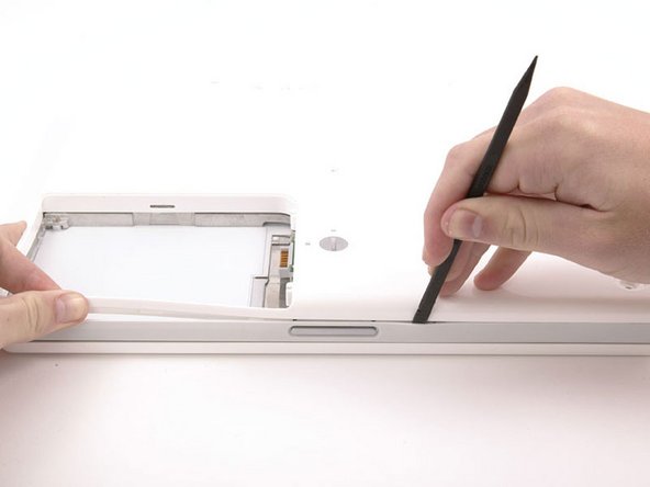
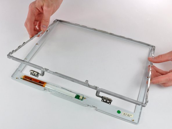
    • Use your thumbs to slightly separate the rear bezel from the front bezel.

    • It is helpful to hold the opposing corner of the display stationary to aid in flexing the rear bezel away from the display.

  47. Este paso está sin traducir. Ayuda a traducirlo

    : paso 47, imagen 1 de 3 : paso 47, imagen 2 de 3 : paso 47, imagen 3 de 3
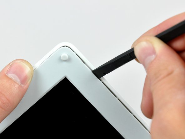
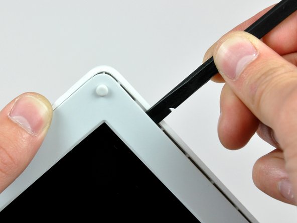
    • Insert the flat end of a spudger into the gap between the front and rear bezels.

    • Rotate your spudger until it is parallel to the front face of the display.

    • Run the spudger around the perimeter of the display to separate the rear bezel from its retaining clips.

  48. Este paso está sin traducir. Ayuda a traducirlo

    : paso 48, imagen 1 de 1
    • Lift the rear bezel off the display.

  49. Este paso está sin traducir. Ayuda a traducirlo

    : paso 49, imagen 1 de 2 : paso 49, imagen 2 de 2
    • Remove the pieces of readily removable tape from around the perimeter of the display.

    • Carefully remove the aluminum tape covering the display data cable connection.

  50. Este paso está sin traducir. Ayuda a traducirlo

    : paso 50, imagen 1 de 2 : paso 50, imagen 2 de 2
    • Remove the single screw inserted through the piece of EMI tape near the bottom edge of the display.

    • Use the tip of a spudger to remove the small washer under the screw you just removed.

  51. Este paso está sin traducir. Ayuda a traducirlo

    : paso 51, imagen 1 de 1
    • Peel the aluminum/EMI tape off the cast aluminum frame of the clutch hinges.

    • It is not necessary to peel the tape off the thin steel LCD cover.

  52. Este paso está sin traducir. Ayuda a traducirlo

    : paso 52, imagen 1 de 2 : paso 52, imagen 2 de 2
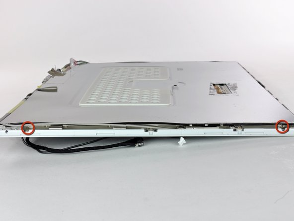
    • Remove the two Phillips screws securing each side of the LCD to the clutch hinge frame (four screws total).

  53. Este paso está sin traducir. Ayuda a traducirlo

    : paso 53, imagen 1 de 1
    • Lift the thin steel LCD cover off the LCD.

  54. Este paso está sin traducir. Ayuda a traducirlo

    : paso 54, imagen 1 de 1
    • Remove the second of the two Phillips screws securing the clutch cover to the cast aluminum frame of the clutch hinges.

  55. Este paso está sin traducir. Ayuda a traducirlo

    : paso 55, imagen 1 de 3 : paso 55, imagen 2 de 3 : paso 55, imagen 3 de 3
    • Pull the clutch cover away from the front of the display.

    • Keep track of the two covers that close the ends of the clutch cover. The third picture shows their correct orientation on the clutch cover.

  56. Este paso está sin traducir. Ayuda a traducirlo

    : paso 56, imagen 1 de 1
    • Remove the pieces of tape covering the display data and microphone cables near the bottom edge of the display.

  57. Este paso está sin traducir. Ayuda a traducirlo

    : paso 57, imagen 1 de 1
    • Disconnect the display data cable by pulling its connector away from the socket on the LCD.

    • Pull the connector parallel to the face of the LCD.

    • Remove the display data cable from the display.

  58. Este paso está sin traducir. Ayuda a traducirlo

    : paso 58, imagen 1 de 2 : paso 58, imagen 2 de 2
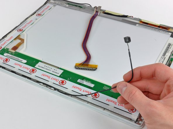
    • Use the tip of a spudger to lift the microphone out of the front bezel.

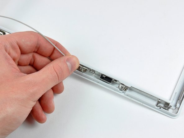
    • De-route the microphone cable from around the top and side of the display.

  59. Este paso está sin traducir. Ayuda a traducirlo

    : paso 59, imagen 1 de 1
    • Remove the display data cable from the display.

  60. Este paso está sin traducir. Ayuda a traducirlo

    : paso 60, imagen 1 de 2 : paso 60, imagen 2 de 2
    • Remove the two pieces of tape covering the inverter/AirPort cables along the lower edge of the display.

    • Carefully peel the inverter cable ground strap off the cast aluminum frame of the clutch hinges.

  61. Este paso está sin traducir. Ayuda a traducirlo

    : paso 61, imagen 1 de 2 : paso 61, imagen 2 de 2
    • Disconnect the backlight cable from the inverter.

    • It is helpful to use a spudger to push the backlight connector away from its socket while you lightly pull its cables away from the inverter.

  62. Este paso está sin traducir. Ayuda a traducirlo

    : paso 62, imagen 1 de 1
    • Lift the LCD out of the display assembly.

    • It may be helpful to press the latch release button and open your display slightly to push the LCD out of the display assembly.

  63. Este paso está sin traducir. Ayuda a traducirlo

    : paso 63, imagen 1 de 1
    • Remove the single Phillips screw securing the reed switch board to the front bezel.

    • Carefully lift the reed switch board off the metal frame of the clutch hinges.

  64. Este paso está sin traducir. Ayuda a traducirlo

    : paso 64, imagen 1 de 2 : paso 64, imagen 2 de 2
    • Remove the two Phillips screws securing the right AirPort antenna to the clutch hinge frame.

    • Carefully lift the right AirPort antenna off the clutch hinge frame.

  65. Este paso está sin traducir. Ayuda a traducirlo

    : paso 65, imagen 1 de 2 : paso 65, imagen 2 de 2
    • Remove the two Phillips screws securing the left AirPort antenna to the clutch hinge frame.

    • Carefully lift the left AirPort antenna off the clutch hinge frame.

  66. Este paso está sin traducir. Ayuda a traducirlo

    : paso 66, imagen 1 de 1
    • Use the flat end of a spudger to remove the antenna board from the front bezel.

    • The antenna board is very thin and delicate.

  67. Este paso está sin traducir. Ayuda a traducirlo

    : paso 67, imagen 1 de 2 : paso 67, imagen 2 de 2
    • Remove the single Phillips screw securing the front bezel to the middle of the cast aluminum clutch hinge frame.

    • Carefully bend the front display bezel away from the clutch hinges as you slide the two AirPort antennas out from under the clutch hinge frame.

  68. Este paso está sin traducir. Ayuda a traducirlo

    : paso 68, imagen 1 de 2 : paso 68, imagen 2 de 2
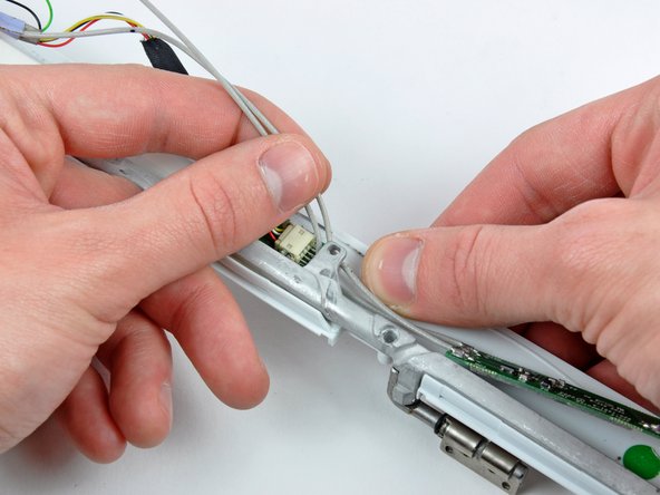
    • While pulling the inverter cable away from its socket on the inverter board, use the tip of a spudger to push the connector out of its socket.

    • If the connector won't budge from its socket, insert a metal spudger or similar tool into the gap between the connector and its socket and twist to separate the two pieces.

  69. Este paso está sin traducir. Ayuda a traducirlo

    : paso 69, imagen 1 de 2 : paso 69, imagen 2 de 2
    • Remove the six Phillips screws securing the clutch hinges to the front display bezel.

    • Lift the clutch hinges off the front display bezel.

  70. Este paso está sin traducir. Ayuda a traducirlo

    : paso 70, imagen 1 de 2 : paso 70, imagen 2 de 2
    • Insert the flat end of a spudger between the display inverter and the front display bezel near the center of the inverter.

    • Run the spudger along the length of the display inverter, separating it from the adhesive securing it to the front display bezel.

    • Lift the inverter out of the front display bezel.

  71. Este paso está sin traducir. Ayuda a traducirlo

    : paso 71, imagen 1 de 1
    • Front bezel remains.

Linea de Meta

3 personas más completaron esta guía.

Documentos Adjuntos

0 comentarios

Agregar Comentario

Ver Estadísticas:

Ultimas 24 horas: 2

Ultimos 7 días: 6

Ultimos 30 días: 8

Todo El Tiempo: 3,428