Esta versión puede contener ediciones incorrectas. Cambie a la última instantánea verificada.
Qué necesitas
-
-
Utiliza la punta del dedo para tirar de la lengüeta de liberación de la batería hacia el centro de la D70.
-
Abre la tapa del portapilas y gíralo para separarlo de la cubierta inferior.
-
-
-
Retira los siguientes ocho tornillos que fijan la cubierta inferior a la D70:
-
Seis tornillos Phillips de 5,8 mm
-
Un tornillo Phillips de 10,7 mm
-
Un tornillo Phillips de 8,2 mm
-
-
Este paso está sin traducir. Ayuda a traducirlo
-
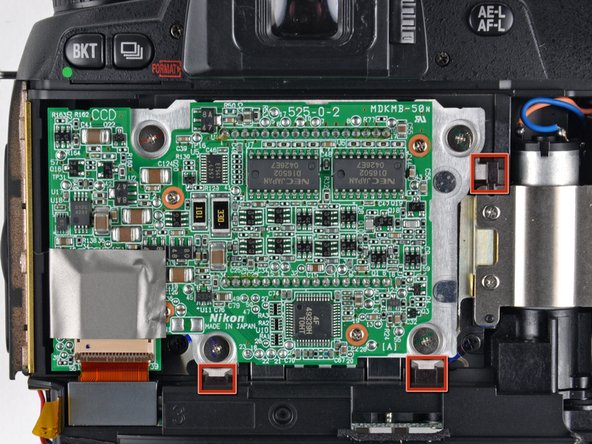
Remove the four ZIF ribbon cables highlighted in red by using the following procedure:
-
Use your fingernail to flip up the ZIF cable retaining flap on each socket.
-
Pull the ribbon cable straight out of its socket.
-
-
Este paso está sin traducir. Ayuda a traducirlo
-
Carefully peel back the piece of tape covering the Compact Flash ribbon cable socket.
-
-
Este paso está sin traducir. Ayuda a traducirlo
-
Use your fingernails to carefully pull the ZIF cable lock away from its socket.
-
Use a pair of tweezers to pull the Compact Flash ribbon cable out of its socket.
-
-
-
Este paso está sin traducir. Ayuda a traducirlo
-
Remove the four 4.3 mm Phillips screws securing the memory compression board to the D70.
-
-
Este paso está sin traducir. Ayuda a traducirlo
-
Use a pair of tweezers to pull the USB connector bracket away from the edge of the memory compression board.
-
-
Este paso está sin traducir. Ayuda a traducirlo
-
Grab the memory compression board by its edges at the position shown in the first picture.
-
Pull the memory compression board straight up off the DC/DC board to avoid damaging the connector on the underside of the memory compression board.
-
-
Este paso está sin traducir. Ayuda a traducirlo
-
De-route the two leads routed over the connector boxed in yellow.
-
Use your thumbnails to push the connector out of its socket.
-
-
Este paso está sin traducir. Ayuda a traducirlo
-
Remove the two Phillips screws securing the grip side of the rear cover to the D70.
-
-
Este paso está sin traducir. Ayuda a traducirlo
-
Remove the two Phillips screws securing the DC-In side of the rear cover to the D70.
-
-
Este paso está sin traducir. Ayuda a traducirlo
-
Carefully pull the sides of the rear cover away from the body of the D70.
-
Pull the rear cover off the body of the D70, minding the LCD board ribbon cable that may get caught.
-
-
Este paso está sin traducir. Ayuda a traducirlo
-
Peel back the piece of tape connecting the iron core around the CCD board ribbon cable to the inner case.
-
-
Este paso está sin traducir. Ayuda a traducirlo
-
Remove the four 4.8 mm Phillips screws securing the CCD board to the D70.
-
-
Este paso está sin traducir. Ayuda a traducirlo
-
Remove the CCD board from the D70, minding any cables that may get caught.
-


Cancelar: No complete esta guía.
25 personas más completaron esta guía.

2 comentarios
Great instructions.
One important note: When re-installing the CCD board ribbon cable into the CCD board, the cable will go into the connector about 2mm and feel like it's seated. However, the cable must go 3mm-4mm into the connector. Otherwise, you will get a "This Card Cannot Be Used" error message each time you depress the shutter button.
Great article.