Saltar al contenido principal

Esta versión puede contener ediciones incorrectas. Cambie a la última instantánea verificada.

Qué necesitas

  1. , Tapa de acceso: paso 1, imagen 1 de 1
    • Apoya tu iMac con la pantalla hacia abajo y con la parte inferior mirando hacia ti.

    • Soltar el unico tornillo Phillips ubicado en el centro de la trampilla de acceso

    • Este tornillo es único para la trampilla de acceso

    • Quitar la trampilla de acceso del iMac

  2. , Panel de cristal: paso 2, imagen 1 de 2 , Panel de cristal: paso 2, imagen 2 de 2
    Herramienta utilizada en este paso:
    Heavy-Duty Suction Cups (Pair)
    $14.95
    Comprar
    • El panel de cristal está fijado con 1 imán en cada esquina de la pantalla.

    • Coloca dos ventosas en las esquinas opuestas del panel de cristal.

    • Para colocar las ventosas que vendemos, primero coloca la ventosa con el asa móvil paralela a la cara del panel de vidrio. Mientras sujeta ligeramente la ventosa contra el cristal, levanta el mango móvil hasta que quede paralelo al otro mango.

    • Si las ventosas no se enganchan bien, pruebe de limpiar tanto el cristal como las ventosas con algún limpiador suave.

  3. : paso 3, imagen 1 de 1
    • Con cuidado retira el panel de cristal del iMac

    • El panel de cristal tiene varios pins de posicionamiento. Para evitar romper estos pins, asegúrate de retirar el cristal hacia arriba hasta separarlo completamente del iMac

    • Sé meticuloso limpiando el cristal por la parte de dentro y la pantalla LCD ya que una vez rensamblado puede verse cualquier marca de suciedad cuando se encienda el monitor.

    • Cuando cambies el cristal, asegúrate de que no haya nada entre el cristal y el marco. Los cables sueltos podrían dañarse o romper el cristal.

  4. Este paso está sin traducir. Ayuda a traducirlo

    : paso 4, imagen 1 de 1
    • Remove the following 12 screws securing the front bezel to the rear case:

    • Eight 13 mm T8 Torx.

    • Four 25 mm T8 Torx.

    • On the 24" iMac Intel Model A1225, the bottom center two screws are long (26mm), four on sides (two left, two right) are medium (18mm), and the remaining 6 (four top, two bottom corners) are short (14mm).

  5. Este paso está sin traducir. Ayuda a traducirlo

    : paso 5, imagen 1 de 2 : paso 5, imagen 2 de 2
    • The front bezel is still attached to the iMac by the microphone cable.

    • Gently lift the front bezel from its top edge off the rear case.

    • Once the top edge of the front bezel has cleared the rear case, rotate the front bezel toward the stand and lift it off the rear case.

    • Rotate the front bezel away from the rest of the device and lay it above the top edge of the iMac.

    • When reinstalling the front bezel, start at the lower edge and make sure it is flush with the rear case before lowering the top edge onto the iMac.

  6. Este paso está sin traducir. Ayuda a traducirlo

    : paso 6, imagen 1 de 1
    • Disconnect the microphone cable connector, removing tape as necessary.

    • For the front bezel to sit properly, be sure to tuck the microphone cable and connector into the void next to the camera board.

  7. Este paso está sin traducir. Ayuda a traducirlo

    : paso 7, imagen 1 de 3 : paso 7, imagen 2 de 3 : paso 7, imagen 3 de 3
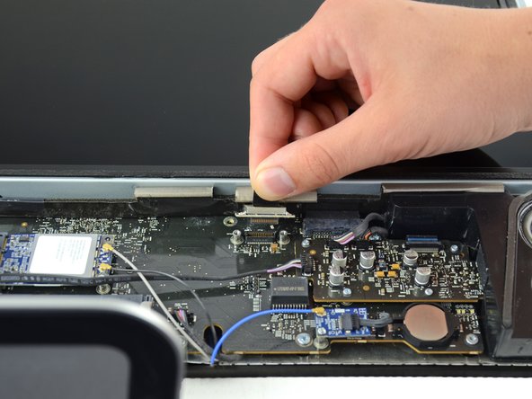
    • Remove the two 5.3 mm T6 torx screws from the LCD connector.

    • Firmly grasp the pull tab on top of the connector and pull it straight up out of its port.

    • Make sure that you are pulling the tab and not the connector cable.

  8. Este paso está sin traducir. Ayuda a traducirlo

    : paso 8, imagen 1 de 1
    • Remove the eight T8 Torx screws securing the display panel to the rear case.

    • The iMac shown is a 20" model, but the screw locations should be approximately correct.

  9. Este paso está sin traducir. Ayuda a traducirlo

    : paso 9, imagen 1 de 3 : paso 9, imagen 2 de 3 : paso 9, imagen 3 de 3
    • Place your hands on either side of the bottom of the display panel, and lift it up enough that you can reach the connectors inside.

    • Do not try to remove the display panel completely as it is still connected to the rest of the device.

    • While holding the display panel up with one hand, locate and remove the display thermal sensor cable from its connector.

  10. Este paso está sin traducir. Ayuda a traducirlo

    : paso 10, imagen 1 de 2 : paso 10, imagen 2 de 2
    • While still holding the display panel up, use two fingers to firmly push down on the power supply cable connector from its socket.

    • Be very careful not to touch the exposed face of the power supply to avoid electric shock from the many large capacitors attached to the other side of the board.

  11. Este paso está sin traducir. Ayuda a traducirlo

    : paso 11, imagen 1 de 1
    • Lift and remove the display panel from the device.

  12. Este paso está sin traducir. Ayuda a traducirlo

    : paso 12, imagen 1 de 2 : paso 12, imagen 2 de 2
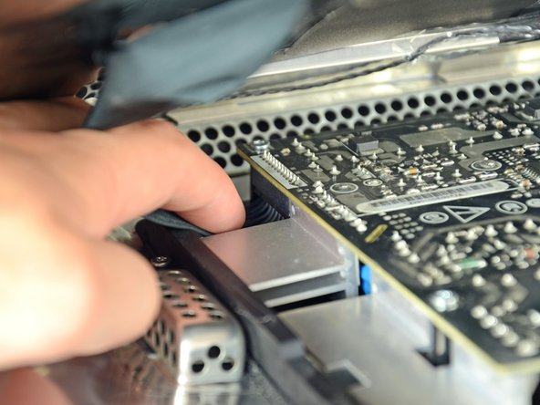
    • Peel off the tape holding the optical drive in place.

    • Remove the two 7.1 mm T10 torx screws.

  13. Este paso está sin traducir. Ayuda a traducirlo

    : paso 13, imagen 1 de 3 : paso 13, imagen 2 de 3 : paso 13, imagen 3 de 3
    • Firmly grab the optical drive connector and pull it straight out of the optical drive.

    • Remove the optical drive from the device.

  14. Este paso está sin traducir. Ayuda a traducirlo

    : paso 14, imagen 1 de 1
    • Remove the piece of foam tape covering the optical drive thermal sensor.

  15. Este paso está sin traducir. Ayuda a traducirlo

    : paso 15, imagen 1 de 1
    • To remove the optical drive thermal sensor, use the tip of a spudger to lift the center finger of the thermal sensor bracket while applying slight tension to the thermal sensor cable.

    • If the thermal sensor is stuck to the optical drive, skip to the next step.

  16. Este paso está sin traducir. Ayuda a traducirlo

    : paso 16, imagen 1 de 1
    • Use the flat end of a spudger to pry the optical drive thermal sensor bracket up off the adhesive securing it to the optical drive.

    • If the adhesive gets dirty or will not stick to your new optical drive, place some double-sided tape under the two semicircular ears of the thermal sensor bracket.

  17. Este paso está sin traducir. Ayuda a traducirlo

    : paso 17, imagen 1 de 1
    • Use a spudger to remove the small piece of EMI foam from the bottom of the optical drive.

    • Don't forget to transfer this to your new drive.

  18. Este paso está sin traducir. Ayuda a traducirlo

    : paso 18, imagen 1 de 1
    • Peel the EMI tape off the optical drive.

    • Don't forget to transfer this to your new optical drive.

  19. Este paso está sin traducir. Ayuda a traducirlo

    : paso 19, imagen 1 de 2 : paso 19, imagen 2 de 2
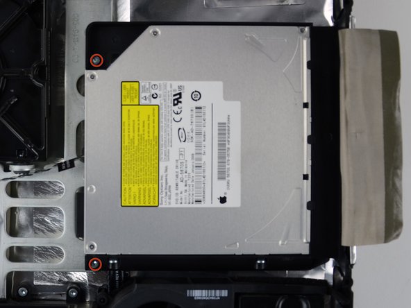
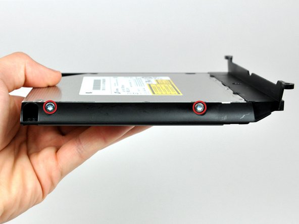
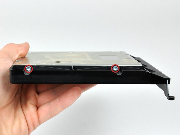
    • Remove the two T10 Torx screws from both sides of the optical drive (four screws total).

  20. Este paso está sin traducir. Ayuda a traducirlo

    : paso 20, imagen 1 de 1
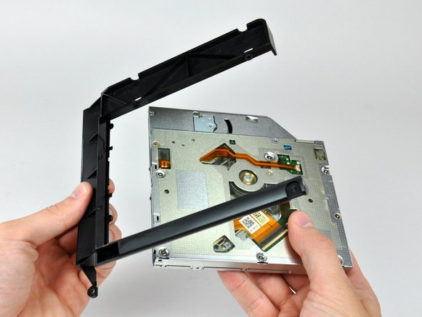
    • Use the tip of a spudger to press each of the optical drive bracket tabs out of their slots on the bottom of the optical drive.

  21. Este paso está sin traducir. Ayuda a traducirlo

    : paso 21, imagen 1 de 2 : paso 21, imagen 2 de 2
    • Rotate the optical drive bracket slightly away from the optical drive.

    • Pull the optical drive bracket away from the open end of the optical drive, minding any tabs that may get caught.

    • If you have a disk or anything else stuck inside your optical drive, we have a guide to fix it.

  22. , Placa Frontal de la Carcasa de la Unidad Óptica: paso 22, imagen 1 de 1
    • Retira los tres tornillos Phillips de 3,0 mm de la carcasa de la bahía óptica.

  23. : paso 23, imagen 1 de 3 : paso 23, imagen 2 de 3 : paso 23, imagen 3 de 3
    • Comenzando desde el borde izquierdo, tira suavemente para abrir la carcasa de la bahía óptica.

    • Continúa tirando para abrir las dos mitades del recinto hasta que se separen.

  24. : paso 24, imagen 1 de 1
    • Quita los dos tornillos Phillips de 3,0 mm que sujetan la placa frontal a la carcasa del compartimiento óptico.

  25. : paso 25, imagen 1 de 3 : paso 25, imagen 2 de 3 : paso 25, imagen 3 de 3
    • Levanta la placa frontal de plástico negro para sacarla del gabinete del compartimiento óptico.

    • Ya no necesitarás la placa frontal ni los dos tornillos Phillips que la mantenían en su lugar. Deja esas piezas a un lado si alguna vez deseas volver a colocar la placa frontal en la carcasa.

    • Vuelve a ensamblar la carcasa del compartimiento óptico sin la placa frontal, reutilizando los tres tornillos Phillips originales de 3,0 mm para mantenerlo intacto.

  26. , Disco Duro Doble: paso 26, imagen 1 de 2 , Disco Duro Doble: paso 26, imagen 2 de 2
    • Retira el posicionador de plástico de la carcasa de la unidad de disco duro del compartimiento óptico presionando uno de los clips a cada lado y levantándolo hacia arriba y sacándolo de la carcasa.

  27. : paso 27, imagen 1 de 3 : paso 27, imagen 2 de 3 : paso 27, imagen 3 de 3
    • Asegúrate de que los conectores del disco duro estén hacia abajo antes de colocarlo en la carcasa.

    • Coloca con cuidado el disco duro en la ranura para discos duros de la carcasa.

    • Mientras sostienes firmemente la carcasa en su lugar con una mano, usa la otra mano para presionar el disco duro en los conectores de la carcasa.

  28. : paso 28, imagen 1 de 2 : paso 28, imagen 2 de 2
    • Una vez que el disco duro esté ajustado, vuelve a insertar el posicionador de plástico mientras sujetas el disco duro contra la parte inferior de la carcasa.

    • Vuelve a conectar cualquier cable que hayas quitado de la unidad óptica original en la carcasa del compartimiento óptico.

Linea de Meta

47 personas más completaron esta guía.

Brittany McCrigler

Miembro Desde 03/05/12

89,017 Reputación

131 Guías creadas

Equipo

iFixit Miembro de iFixit

Staff

135 Miembros

17,128 Guías creadas

3 comentarios

Many many many thanks, everything went fine with my iMac early 2009 which is now ready for a second life with my kids :)

davbouchard - Contestar

Mystery: I have removed and replaced my bezel many times - most recently to repair the vid card. However this time while powering up fine before replacing the bezel - now, once bezel is in place it won’t power on - but I hear a ‘click’ in the lower right corner after pushing the power. But then, if I pull the bezel back about an inch from the top - it starts >Something seems to be ‘shorting’ ?

Albert not Einstein - Contestar

Many thanks Brittany and ifixit, no problems encountered and it took me about 2 hours only because I checked and double checked everything I did. iMac early 2009, saved it from the scrap heap for a while longer.

Derek Anson - Contestar

Agregar Comentario

Ver Estadísticas:

Ultimas 24 horas: 3

Ultimos 7 días: 27

Ultimos 30 días: 115

Todo El Tiempo: 66,741