Saltar al contenido principal

Esta versión puede contener ediciones incorrectas. Cambie a la última instantánea verificada.

Qué necesitas

  1. , Cubierta trasera: paso 1, imagen 1 de 2 , Cubierta trasera: paso 1, imagen 2 de 2
    • Antes de desmontar tu iPhone, asegúrate de que este apagado.

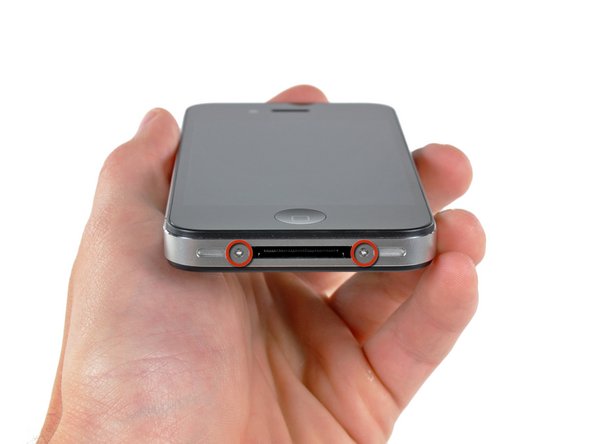
    • La caja posterior de tu iPhone 4 puede fijarse bien con dos tornillos Phillips #000 o bien con tornillos Apple de 5-Puntos (segunda imagen). Comprueba cuáles tienes y asegúrate de que tienes el destornillador adecuado para retirarlos.

    • Retira los dos tornillos Pentalobe o Phillips #000 de 3.6 mm que están junto al conector para el cargador.

    • El Destornillador de 5-Puntos solo de ser utilizado una vez, ya que tiene la posibilidad de barrer los tornillos.

  2. : paso 2, imagen 1 de 2 : paso 2, imagen 2 de 2
    • Empuja el panel trasero hacia el borde superior del iPhone.

    • El panel se moverá cerca de 2mm.

  3. : paso 3, imagen 1 de 1
    • Pincha el panel trasero con tus dedos y levántalo del iPhone. Alternativamente, usa una Pequeña Ventosa de Succión.

    • Ten cuidado de no dañar los clips de plástico unidos al panel trasero.

    • Si estas instalando un nuevo panel trasero, asegúrate de remover el plástico protectivo del interior de los lentes de la cámara y el sticker de la gran área negra cerca de los lentes.

  4. , Batería: paso 4, imagen 1 de 1
    • Remueve el único tornillo de 2.5 mm Phillips que asegura el conector de la batería a la tarjeta lógica.

    • Algunos dispositivos tienen dos tornillos, uno que sostiene la almohadilla de contacto que esta localizado sobre el tornillo indicado en rojo en la foto.

  5. : paso 5, imagen 1 de 1
    • Usa una herramienta de plástico de apertura para gentilmente hacer palanca en el conector de la batería de su socket en la tarjeta lógica.

    • Haz palanca desde el superior e inferior del bracket del conector--no hay algo como un lado sobresaliente, y puedes dañar el conector.

    • Ten mucho cuidado de solo hacer palanca en el conector de la batería y no en el socket de la tarjeta lógica. SI haces palanca en el socket de la tarjeta lógica puedes romperlo por completo.

    • Remueve el clip de metal que cubre el conector de la antena.

  6. : paso 6, imagen 1 de 3 : paso 6, imagen 2 de 3 : paso 6, imagen 3 de 3
    • Usa la pestaña de plástico clara para levantar gentilmente la batería fuera del iPhone.

    • Si la pestaña se rompe antes que la batería este liberada, aplica unas gotas de alcohol isopropílico de alta concentración (90%) debajo del borde de la batería. Espera cerca de un minuto para que la solución de alcohol afloje el pegamento. Cuidadosamente desliza una esp´átula debjo de la pestaña de la batería para soltar el adhesivo.

    • Hacer palanca en otros lugares puede causar daño. No trates de levantar la batería haciendo fuerza. Si es necesario, aplica más gotas de alcohol para aflojar más el adhesivo. Nunca deformes o pinches la batería con tu herramienta de palanqueo.

    • Si hay solución de alcohol restante en el teléfono, límpialo cuidadosamente o permite que se seque antes de instalar la batería nueva.

    • Si tu batería de reemplazo viene en una funda de plástico, remuévela antes de instalarla jalándola desde el cable plano.

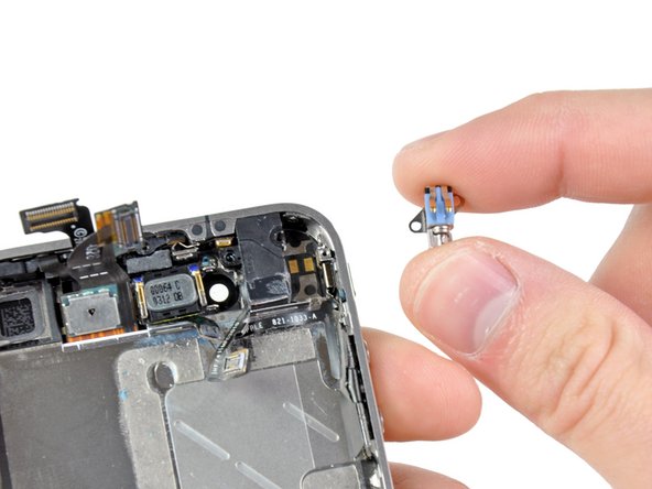
    • Antes de reconectar el conector de la batería, asegúrate que el clip de contacto (mostrado en rojo) este propiamente posicionado a lado del conector de la batería.

    • Antes de reensamblar, limpia los puntos de contacto metal-con-metal con un des-engrasante como windex. El aceite de tus dedos tiene el potencial de causar problemas de interferencia inalámbrica.

    • Realiza un hard reset después del reensamble. Esto previene varios problemas y simplifica la resolución de problemas.

  7. Este paso está sin traducir. Ayuda a traducirlo

    : paso 7, imagen 1 de 2 : paso 7, imagen 2 de 2
    • Use a SIM card eject tool or a paperclip to eject the SIM card and its holder.

    • This may require a significant amount of force.

    • Remove the SIM card and its holder.

  8. Este paso está sin traducir. Ayuda a traducirlo

    : paso 8, imagen 1 de 2 : paso 8, imagen 2 de 2
    • Remove the following two screws:

    • One 1.2 mm Phillips

    • One 1.6 mm Phillips

    • Remove the thin steel dock connector cable cover from the iPhone.

    • Before reassembly, be sure to clean all metal-to-metal contact points on the dock connector cable cover with a de-greaser such as windex. The oils on your fingers have the potential to cause wireless interference issues.

  9. Este paso está sin traducir. Ayuda a traducirlo

    : paso 9, imagen 1 de 2 : paso 9, imagen 2 de 2
    • Use an iPod opening tool to gently pry the dock cable connector up off the logic board from both short ends of the connector.

  10. Este paso está sin traducir. Ayuda a traducirlo

    : paso 10, imagen 1 de 2 : paso 10, imagen 2 de 2
    • Carefully peel the dock ribbon cable off the logic board and the lower speaker enclosure.

    • Do not use excessive force to peel the dock ribbon cable off the logic board. Doing so may tear the cable.

  11. Este paso está sin traducir. Ayuda a traducirlo

    : paso 11, imagen 1 de 1
    • Use a plastic opening tool to pry the lower antenna connector up off its socket on the logic board.

  12. Este paso está sin traducir. Ayuda a traducirlo

    : paso 12, imagen 1 de 1
    • Remove the 1.9 mm Phillips screw securing the bottom of the logic board to the inner case.

  13. Este paso está sin traducir. Ayuda a traducirlo

    : paso 13, imagen 1 de 1
    • Remove the following five screws securing the Wi-Fi antenna to the logic board:

    • One 2.3 mm Phillips

    • Two 1.6 mm Phillips

    • One 1.4 mm Phillips

    • One 4.8 mm Phillips

    • When re-assembling, start off with replacing the 4.8 mm Philips screw first, then the 2.3 mm. This is to ensure there is no mix-up, and avoid rendering the LCD and digitizer useless.

    • Also make sure to put the long 4.8 mm Philips back in correctly when reassembling. This is the ground for the Wi-Fi antenna and is often the culprit if you are having bad Wi-Fi reception after reassembly.

  14. : paso 14, imagen 1 de 3 : paso 14, imagen 2 de 3 : paso 14, imagen 3 de 3
    • Utilice una herramienta de apertura de iPod para desprender con cuidado la tapa de la antena Wi-Fi de la tarjeta lógica.

    • Insertar traducción aquí

    • Remueva la antena Wi-Fi del iPhone. Procure no extraviar los clips de metal de la tapa superior donde ajustan los tornillos de 4.8 mm. Esta es la causa por la que regularmente hay fallos en la señal inalámbrica cuando se reensambla.

    • Antes de reensamblar, asegúrese de limpiar todos los puntos de contacto metal-a-metal en el conector con un desengrasante como el Windex. La grasa de sus dedos tiene el potencia de causar interferencia a las partes inalambricas. No deje Windex en los conectores.

  15. : paso 15, imagen 1 de 2 : paso 15, imagen 2 de 2
    • Utilice la herramienta de apertura para iPod para retirar cuidadosamente el conector de la cámara posterior de su socket en la tarjeta lógica.

    • Remover la cámara posterior.

  16. : paso 16, imagen 1 de 2 : paso 16, imagen 2 de 2
    • Remover la pequeña etiqueta circular color blanco (es la etiqueta de garantía e indicador de agua) que cubre el tornillo cerca de la pestaña para jalar la bateria.

    • Remover los tornillos Phillips de 2.4 mm que se encontraban ocultos debajo de la etiqueta blanca circular.

  17. Este paso está sin traducir. Ayuda a traducirlo

    : paso 17, imagen 1 de 1
    • Use the edge of a plastic opening tool to gently pry the following connectors up and out of their sockets on the logic board:

    • Digitizer cable (pry from bottom)

    • LCD cable (pry from bottom)

    • Headphone jack/volume button cable (pry from top)

    • Top Microphone/sleep button cable (pry from top)

    • Front camera cable (pry from top)

  18. Este paso está sin traducir. Ayuda a traducirlo

    : paso 18, imagen 1 de 1
    Herramienta utilizada en este paso:
    Standoff Screwdriver for iPhones
    $5.49
    Comprar
    • Remove the 4.8 mm standoff screw near the headphone jack.

    • Standoff screws are best removed using a standoff screwdriver or bit.

    • In a pinch, a small flathead screwdriver will do the job—but use extra caution to ensure it doesn't slip and damage surrounding components.

    • When reassembling the device, this standoff sets the height of the Wi-Fi shield removed in step 13. If not torqued down, the shield will be above the plane of the frame and the back will not slide into place in step 2. The shield should be flush with the headphone jack.

    • When reassembling the motherboard, ensure that its edge sits under the circled standoff, otherwise the screws will not fit.

    • When reassembling ensure that the small rubber spacer attached to the top of the motherboard is in place.

    • Without this part, the motherboard could damage the ribbon cables around it.

  19. Este paso está sin traducir. Ayuda a traducirlo

    : paso 19, imagen 1 de 1
    • Carefully remove the logic board from the iPhone, minding any cables that may get caught.

    • Be careful not to damage the small gold prong (marked in red, near the top) as it's very fragile.

    • On reassembly, be careful not to trap the lower antenna cable beneath the logic board.

  20. Este paso está sin traducir. Ayuda a traducirlo

    : paso 20, imagen 1 de 2 : paso 20, imagen 2 de 2
    • Use the edge of a plastic opening tool to lift the thin steel front camera retainer off the front camera.

    • Remove the front camera retainer.

    • During reassembly, position the clip's tabs on the outside of the receiving metal slots.

  21. Este paso está sin traducir. Ayuda a traducirlo

    : paso 21, imagen 1 de 1
    • Carefully lift the front facing camera out of the iPhone.

    • It may be helpful to use tweezers to reinstall the front camera retainer.

  22. Este paso está sin traducir. Ayuda a traducirlo

    : paso 22, imagen 1 de 2 : paso 22, imagen 2 de 2
    • Remove the following two screws securing the vibrator to the inner frame:

    • One 6 mm Phillips

    • One 1.4 mm Phillips

    • Remove the vibrator from the inner case.

  23. Este paso está sin traducir. Ayuda a traducirlo

    : paso 23, imagen 1 de 1
    • Use the edge of a plastic opening tool to pry the earpiece speaker away from the adhesive securing it to the front panel.

    • Be sure to pry beneath the entire speaker, and not inside it, which may cause it to split open.

  24. Este paso está sin traducir. Ayuda a traducirlo

    : paso 24, imagen 1 de 2 : paso 24, imagen 2 de 2
    • Remove the two Phillips #000 screws securing the power button bracket to the outer case.

    • Take extra care with the display cables, which can prevent easy access to the right-hand screw. The cables are easily damaged.

    • Carefully pull the power button bracket up and out of the outer case.

    • This bracket is made of cast aluminum and is very easily cracked. Proceed with caution.

  25. Este paso está sin traducir. Ayuda a traducirlo

    : paso 25, imagen 1 de 1
    • Use a pair of tweezers to pull the body of the headphone jack out of the outer case.

    • Take extra caution to avoid ripping the thin cable.

  26. Este paso está sin traducir. Ayuda a traducirlo

    : paso 26, imagen 1 de 1
    • Grab the power & sensor cable near the microphone and peel it off the front panel, being careful not to rip it in the process.

    • Take note of the gold, rectangular microphone attached vertically to the case. Take care not to rip it when removing the cable.

  27. Este paso está sin traducir. Ayuda a traducirlo

    : paso 27, imagen 1 de 1
    • If you are replacing the power & sensor cable with a new unit, use the edge of a plastic opening tool to peel the electronic power switch off its metal bracket.

    • Also be sure to transfer the proximity sensor foam/UV-filter adhered to the old power & sensor cable if your new one does not already come with one. It looks like a small square and can be peeled off with tweezers.

    • Transfer the bracket to your new power & sensor cable.

Linea de Meta

509 personas más completaron esta guía.

Documentos Adjuntos

24 comentarios

Be careful removing the headphone adapter, the ribbon is very easy to rib with the metal brace beneath it.

Ryan Bahr - Contestar

Thank you very much for the, it has been very useful for my to change the power and sensor cable.

You are doing a very good job in this web.

rafar1980 - Contestar

Now this is more helpful, than the power button repair guide that they gave us. This one still kind of leaves me hanging on how I'm supposed to put the silver button back into the hole so that it makes contact with the orange dome(aka the powerbutton).

Anthony - Contestar

I replaced the Home button and the Power & Sensor cable, along with battery. Let me explain some caveats with ifixit's parts (OEM Apple parts):

-The power-sensor part does not include a new gasket/filter for the sensor- recommend tweezers and care.

-The power-sensor cable needs the foam pad transferred with the adhesive- extreme care with removal.

-IF the power button isn't working it is likely the cable, not the button.

-I used a small ice cube tray.

-It took me an hour (I had to get up and walk away...frustration factor high with the delicate flex cables and adhesive). Lit magnifier is welcome. Definitely use a spudge stick.

-I broke 2 of the 4 shield/antenna tabs that you need to tuck down from the speaker on re-assembly. I didn't force them, but so easy to press too hard in seating the speaker.

- I do repairs on a grounded-ESD mat and wore wriststrap.

-Right screw on the power button brace is PITA to access...careful pressing on the display flex cables to access the tiny screw. Magnetize your bit!

meekgeek - Contestar

Great guide and perfect web site. It is extremely easy to find what you are looking for and order the components you need.

alessandronapoli - Contestar

Agregar Comentario

Ver Estadísticas:

Ultimas 24 horas: 2

Ultimos 7 días: 18

Ultimos 30 días: 52

Todo El Tiempo: 430,713