Esta versión puede contener ediciones incorrectas. Cambie a la última instantánea verificada.
Qué necesitas
-
-
Si el cristal de la pantalla está agrietado, evita que se siga rompiendo y evita daños corporales durante la reparación pegando el cristal con cinta adhesiva.
-
Coloca tiras superpuestas de cinta de embalar transparente sobre la pantalla del iPad hasta cubrir toda la cara. Para roturas especialmente graves, puede que tengas que poner dos capas.
-
Haz todo lo posible por seguir el resto de la guía tal como se describe. Sin embargo, una vez roto el cristal, es probable que siga agrietándose mientras trabajas, y puede que tengas que utilizar una herramienta de palanca metálica para sacar el cristal.
-
-
-
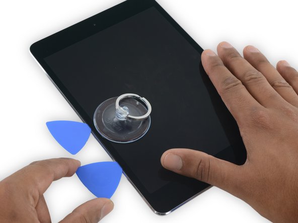
Calienta un iOpener y aplícalo en el borde izquierdo durante dos minutos.
-
-
-
Coloca una ventosa hasta la mitad del lado calentado.
-
Asegúrese de que la taza esté completamente plana en la pantalla para obtener un sello hermético.
-
Mientras sostiene el iPad hacia abajo con una mano, tire de la ventosa para separar ligeramente el conjunto del panel frontal de la carcasa trasera.
-
-
-
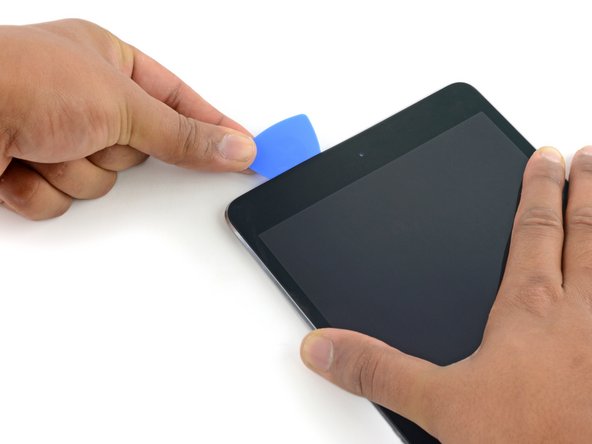
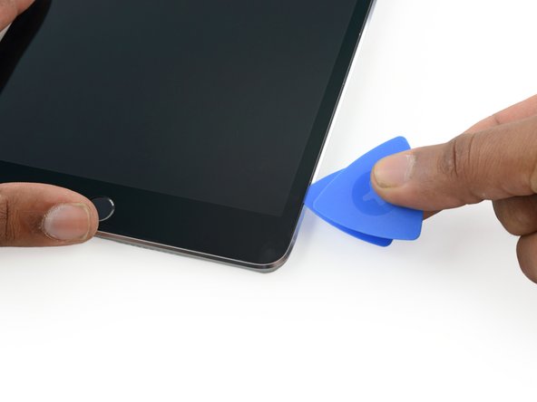
Deja la púa de plástico en el iPad, después de haber pasado la cámara frontal.
-
Coge una segunda púa e insértala a la izquierda de la cámara frontal, justo donde estaba antes la primera púa. Deslízala hacia la esquina para despegar el resto del adhesivo.
-
Deja la segunda púa ahí, para evitar que el adhesivo de la esquina vuelva a pegarse.
-
-
-
-
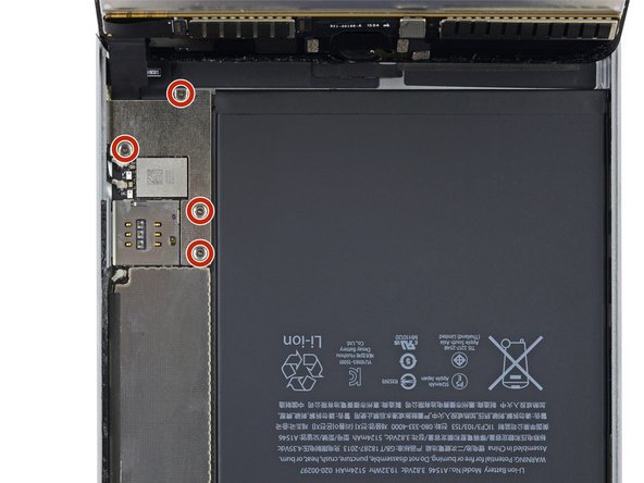
Retira los cuatro tornillos Phillips de 1.2mm que se encuentran sobre el soporte que conecta la batería y la pantalla.
-
-
-
Usa el extremo puntiagudo de un spudger para desconectar el conector de datos de la pantalla de su zócalo en la placa lógica.
-
Usa el extremo puntiagudo de un spudger para desconectar el conector del cable del digitalizador de su zócalo en la placa lógica.
-
-
Este paso está sin traducir. Ayuda a traducirlo
-
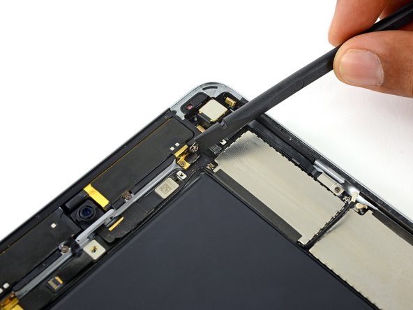
Run the pointed end of a spudger between the looped tape and the plastic cellular antenna housing to make it easier to peel the tape up.
-
-
Este paso está sin traducir. Ayuda a traducirlo
-
Use tweezers to peel up the looped tape adhered over the upper component cable bracket.
-
-
Este paso está sin traducir. Ayuda a traducirlo
-
Remove the following four Phillips screws holding the upper component bracket in place:
-
Two 2.1 mm screws
-
Two 1.2 mm screws
-
-
Este paso está sin traducir. Ayuda a traducirlo
-
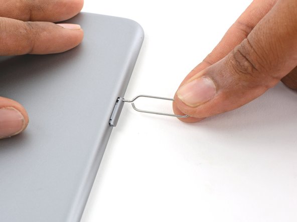
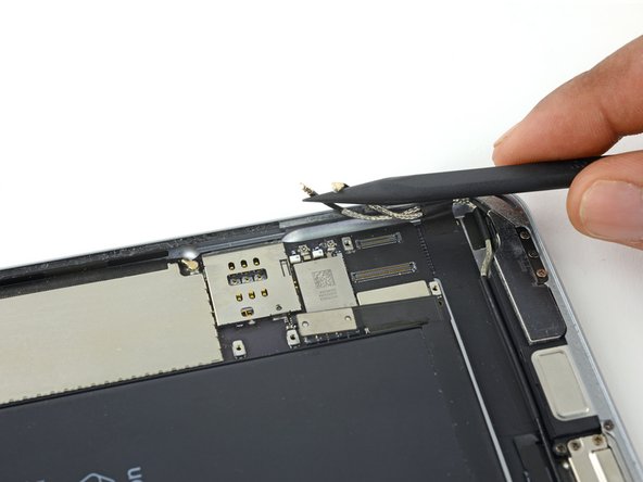
Press a paper clip or SIM eject tool into the SIM eject hole.
-
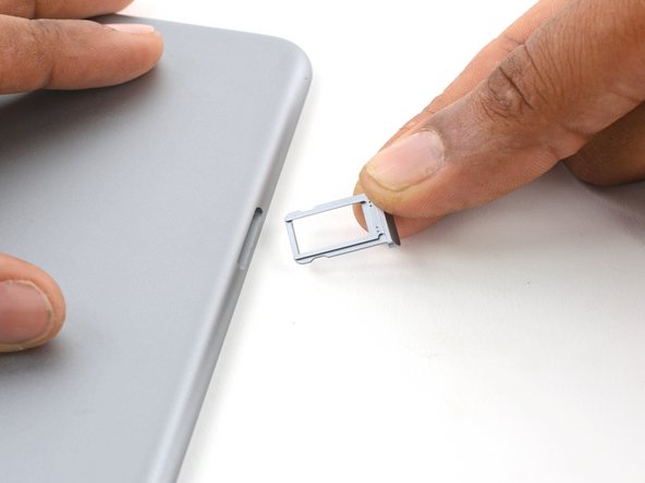
Remove the SIM card tray.
-
-
Este paso está sin traducir. Ayuda a traducirlo
-
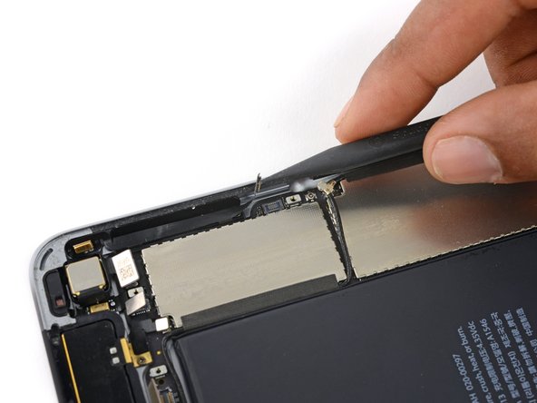
Use a spudger to disconnect the upper antenna interconnect cable from its socket on the logic board.
-
-
Este paso está sin traducir. Ayuda a traducirlo
-
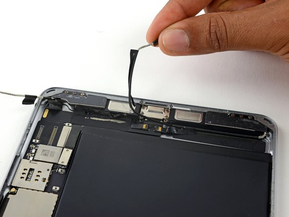
Peel the upper antenna interconnect cable up off the logic board.
-
-
Este paso está sin traducir. Ayuda a traducirlo
-
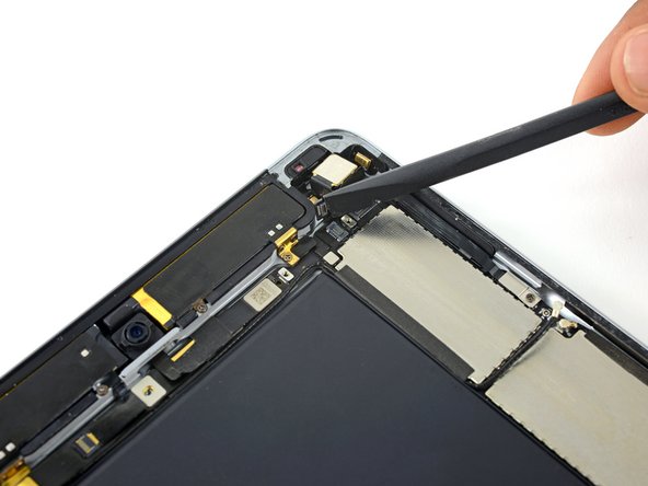
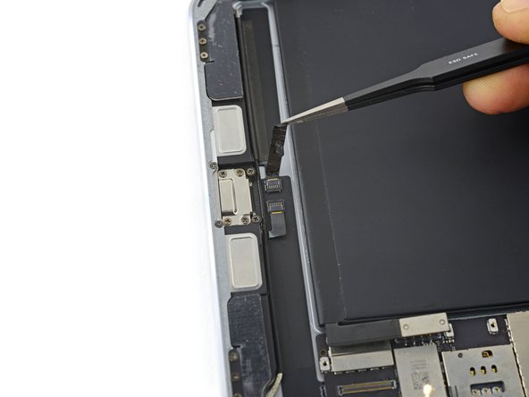
Use the flat end of a spudger to lift the rear-facing camera cable connector from its socket on the logic board.
-
Lift the sensor cable connector from its socket.
-
Disconnect the right cellular antenna from the logic board.
-
-
Este paso está sin traducir. Ayuda a traducirlo
-
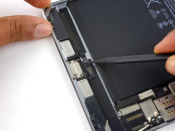
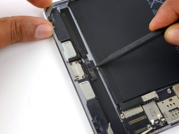
Use the flat end of a spudger to disconnect the front-facing camera press connector.
-
Lift the Facetime camera ribbon cable out of the way and disconnect the headphone jack ribbon cable directly underneath it.
-
-
Este paso está sin traducir. Ayuda a traducirlo
-
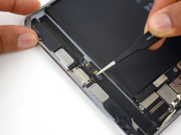
Remove the 1.2 mm Phillips screw securing the volume control cable.
-
-
Este paso está sin traducir. Ayuda a traducirlo
-
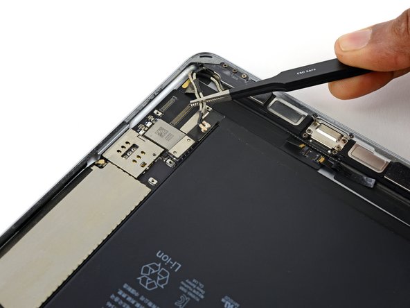
Use the point of a spudger to lift the volume control cable connector from its socket on the logic board.
-
Be careful to lift up only on the connector itself, not the socket on the logic board.
-
-
Este paso está sin traducir. Ayuda a traducirlo
-
Use the point of a spudger to disconnect the two lower antenna interconnect cable connectors.
-
-
Este paso está sin traducir. Ayuda a traducirlo
-
Remove any tape covering the ZIF connectors near the Lightning connector port.
-
-
Este paso está sin traducir. Ayuda a traducirlo
-
Use the tip of a spudger to lift each of the two ZIF connector retaining flaps.
-
-
Este paso está sin traducir. Ayuda a traducirlo
-
Peel the lower antenna interconnect cables away from the corner of the rear case.
-
-
Este paso está sin traducir. Ayuda a traducirlo
-
Peel the left antenna interconnect cable up off the Lightning port cable.
-
-
Este paso está sin traducir. Ayuda a traducirlo
-
Remove the four 1.5 mm Phillips screws securing the Lightning port to the rear case.
-
-
Este paso está sin traducir. Ayuda a traducirlo
-
Begin to gently lift the Lightning connector cable up.
-
-
Este paso está sin traducir. Ayuda a traducirlo
-
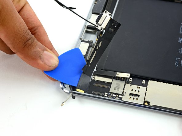
Use an opening pick to separate the adhesive connecting the lightning connector cable to the iPad case.
-
-
Este paso está sin traducir. Ayuda a traducirlo
-
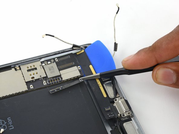
Continue to slide the pick under the Lightning port cable until you reach the end of the logic board.
-
Leave the pick in place to prevent the adhesive from re-adhering.
-
-
Este paso está sin traducir. Ayuda a traducirlo
-
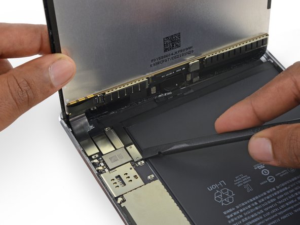
Bend back the battery connector over the battery, out of the way of the logic board.
-
-
Este paso está sin traducir. Ayuda a traducirlo
-
Reheat an iOpener and lay it on the backside of the iPad near the SIM slot for at least two minutes.
-
-
Este paso está sin traducir. Ayuda a traducirlo
-
Once the adhesive has softened, carefully push the opening pick under the logic board.
-
-
Este paso está sin traducir. Ayuda a traducirlo
-
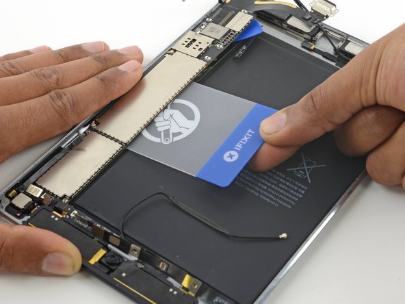
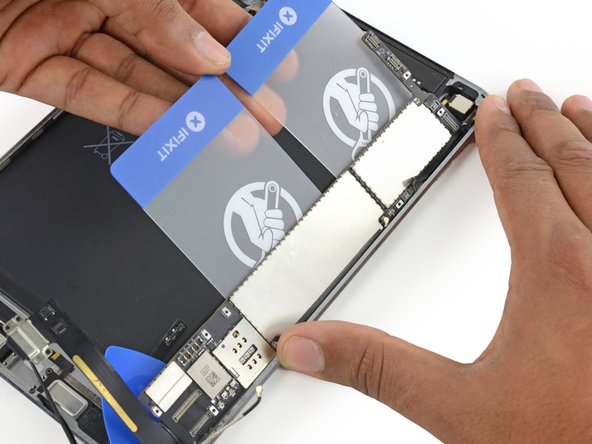
Once the opening pick has lifted a corner of the logic board, you can insert a plastic card under the board.
-
Slide the plastic card under the logic board, toward the top of the iPad, near the cameras.
-
-
Este paso está sin traducir. Ayuda a traducirlo
-
Insert a second plastic card underneath the first one.
-
Slide the second plastic card up to the top edge of the logic board.
-
-
Este paso está sin traducir. Ayuda a traducirlo
-
Lift up on the edges of both plastic cards to pry the logic board from the rear case.
-


Cancelar: No complete esta guía.
7 personas más completaron esta guía.

Un comentario
This guide needs amending urgently before more people destroy their LCD displays by cutting through the tape holding the backlight to the LCD glass, or pushing a pick or other tool between the LCD glass and touchscreen glass.
The guide states:
Don't insert the opening pick any deeper than the black bezel on the side of the display.
This is WRONG and will destroy your display. The black bezel is 5mm wide, this is beyond the 1mm wide adhesive and into the LCD display and backlight assembly. Do not insert anything more than 2mm down the sides of the display.
Any further than 2mm and, like me, you will be looking at a very expensive LCD display replacement.
Thanks IFIXIT.COM for publishing an incorrect guide that has destroyed my display.