Esta versión puede contener ediciones incorrectas. Cambiar a la última instantánea verificada.
Qué necesitas
-
-
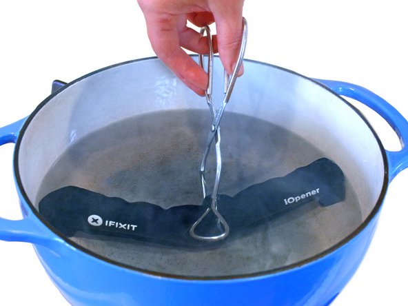
Llena una olla o cacerola con suficiente agua para sumergir completamente el iOpener.
-
Calienta el agua hasta que hierva. Apaga el fuego.
-
Coloca un iOpener en el agua caliente durante 2-3 minutos. Asegúrate de que el iOpener esté completamente sumergido en el agua.
-
Utiliza unas pinzas para extraer el iOpener calentado del agua caliente.
-
Seca bien el iOpener con una toalla.
-
Tu iOpener está listo para ser utilizado. Si necesita recalentar el iOpener, calienta el agua hasta que hierva, apaga el fuego y coloca el iOpener en el agua durante 2-3 minutos.
-
-
-
Si tu cristal de pantalla está agrietado, mantén una mayor rotura contenida y evita daños corporales durante su reparación pegando el vidrio.
-
Coloca tiras superpuestas de cinta de embalaje transparente sobre la pantalla del iPad hasta que toda la cara está cubierta.
-
Haz lo que puedas para seguir el resto de la guía según lo descrito. Sin embargo, una vez que el vidrio se rompe, es probable que continúe agrietándose mientras trabajas, y puede que tengas que usar una herramienta metálica para sacar el vidrio.
-
-
-
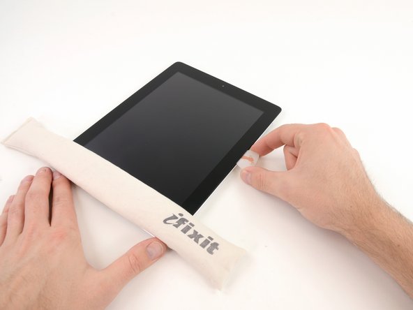
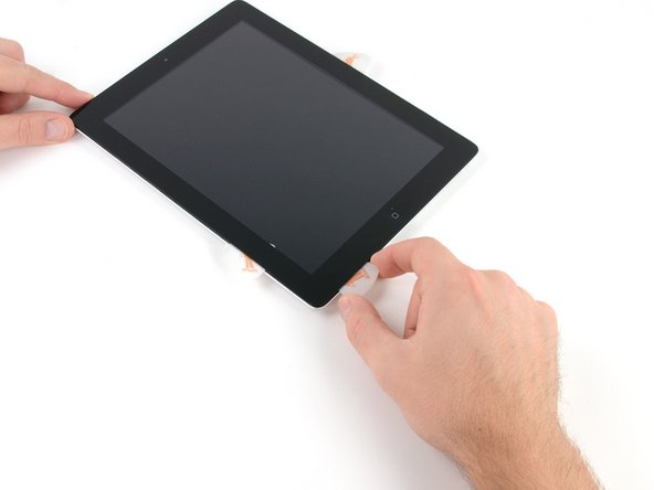
Hay una pequeña brecha en el anillo adhesivo del iPad en la esquina superior derecha del iPad, aproximadamente 2,0 pulgadas (~ 5 cm) desde la parte superior del iPad. Vas a explotar esta debilidad.
-
Alinea la herramienta con el botón de silencio. Inserta la punta de una herramienta de apertura de plástico en el hueco entre el cristal frontal y el bisel de plástico. Basta con insertar la punta de la herramienta de apertura, lo suficiente como para ensanchar la grieta.
-
-
-
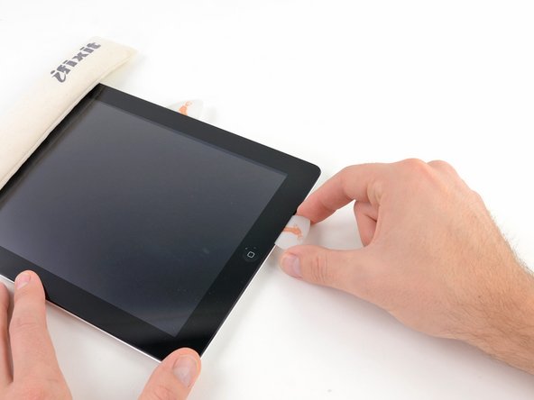
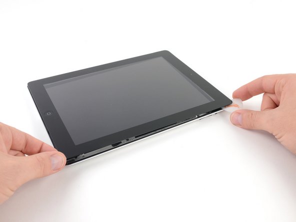
Una vez que haya pasado la antena Wi-FI (aproximadamente 75 mm desde el borde derecho, o justo al lado del botón de inicio) vuelva a insertar la selección de apertura a su profundidad máxima.
-
Desliza la palanca hacia la derecha, liberando el adhesivo que sujeta la antena Wi-Fi al cristal frontal.
-
La antena está conectada a la parte inferior del iPad a través de tornillos y un cable. Este paso separa la antena del panel frontal, asegurando que al retirar el panel, la antena no se dañará.
-
-
-
-
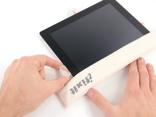
Desliza la púa de apertura a lo largo del borde superior del iPad, tirando ligeramente hacia fuera para rodear el soporte frontal de la cámara.
-
El adhesivo a lo largo de esta sección es muy grueso, y puede requerirse una cantidad justa de fuerza. Trabaja con cuidado y lentamente, asegurándose de no resbalar y dañarse a sí mismo o a tu iPad.
-
-
-
Desliza la púa de apertura a lo largo del borde izquierdo del iPad, liberando el adhesivo a medida que avanza. El adhesivo es delgado debido al digitalizador a lo largo de todo el lado izquierdo. Asegúrate de que la púa no esté más de 10 mm dentro para evitar dañar el digitalizador.
-
-
-
Sosteniendo el iPad por las esquinas superior e inferior derecha, gira el cristal delantero lejos del iPad.
-
Durante el montaje, utiliza un paño de microfibra y aire comprimido para limpiar el polvo o las huellas dactilares de la pantalla LCD antes de volver a instalar el cristal.
-
-
-
Retira los cuatro tornillos Phillips de 2,0 mm que fijan el LCD a la caja trasera.
-
-
Este paso está sin traducir. Ayuda a traducirlo
-
Carefully peel the rubber cover off the metal camera retainer and remove it from the iPad 2.
-
-
Este paso está sin traducir. Ayuda a traducirlo
-
Remove the following two screws:
-
One 3.3 mm Phillips screw
-
One 2.1 mm Phillips screw
-
Lift the metal retainer clip straight up from its recess in the rear panel.
-
-
Este paso está sin traducir. Ayuda a traducirlo
-
Use a plastic opening tool to pry the rear camera connector up from its socket on the upper component board.
-
Remove the rear camera.
-
-
Este paso está sin traducir. Ayuda a traducirlo
-
Use the tip of a spudger to flip the retaining tab on the ZIF connector to release the GPS cable.
-
-
Este paso está sin traducir. Ayuda a traducirlo
-
Remove the following screws from the volume/power button assembly cable:
-
Two 2.5 mm Phillips #000 screws, at a 45º angle securing the power button.
-
Two 5 mm Phillips #000 screws
-
One 2 mm Phillips #000 screw at a 45º angle.
-
-
Este paso está sin traducir. Ayuda a traducirlo
-
Remove the metal bracket securing the rotation lock/silent switch.
-
-
Este paso está sin traducir. Ayuda a traducirlo
-
Pull the power button cable out of the recess in the rear case and bend it out of the way.
-
-
Este paso está sin traducir. Ayuda a traducirlo
-
Use the center screw hole of the volume control bracket to tilt it out toward the edge of the case and then pull it up out of its recess.
-
-
Este paso está sin traducir. Ayuda a traducirlo
-
Gently peel the power and volume button cable away from the rear case.
-
Bend the cable toward the inside of the rear case, but do not attempt to remove it as it is still connected to the upper component board.
-
-
Este paso está sin traducir. Ayuda a traducirlo
-
Remove the rotation lock/silent switch from the rear case.
-
-
Este paso está sin traducir. Ayuda a traducirlo
-
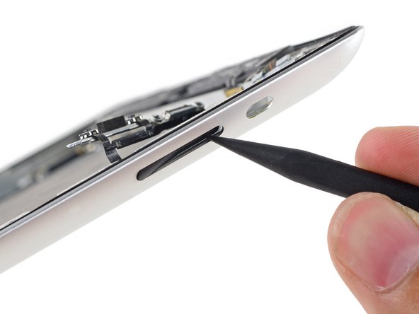
Use the tip of a spudger to push the volume rocker into the interior of the rear case.
-
Remove the volume rocker from the rear case.
-
-
Este paso está sin traducir. Ayuda a traducirlo
-
Use the point of an opening pick to gently peel the Smart Cover sleep/wake sensor up off the rear case.
-
-
Este paso está sin traducir. Ayuda a traducirlo
-
Carefully peel the volume rocker portion of the button cable away from the rear case.
-
-
Este paso está sin traducir. Ayuda a traducirlo
-
Gently peel the last horizontal portion off of the rear case.
-
-
Este paso está sin traducir. Ayuda a traducirlo
-
Remove the single 2 mm Phillips #000 screw from the lower end of the upper component board.
-
-
Este paso está sin traducir. Ayuda a traducirlo
-
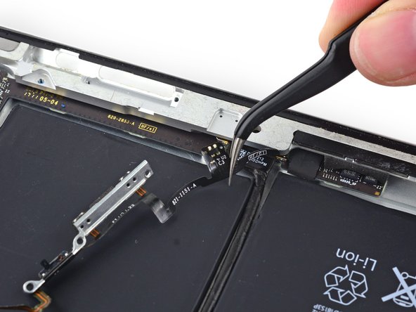
Use a set of tweezers to remove the foam block from between the rear case and the upper component board.
-
-
Este paso está sin traducir. Ayuda a traducirlo
-
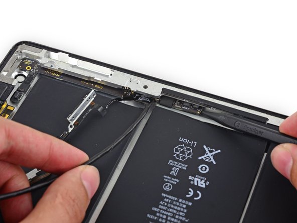
Insert a spudger under the end of the upper component board and gently slide it toward the volume rocker to free the board from adhesive.
-
-
Este paso está sin traducir. Ayuda a traducirlo
-
Insert a spudger under the GPS connector end of the upper component board and lift it up off of its adhesive.
-
-
Este paso está sin traducir. Ayuda a traducirlo
-
Flip up the retaining bar securing the upper component board cable connector.
-
Pull the connector straight out of its socket on the logic board.
-
-
Este paso está sin traducir. Ayuda a traducirlo
-
Lift the end of the upper component board cable up off of the adhesive holding it to the rear case.
-
-
Este paso está sin traducir. Ayuda a traducirlo
-
Insert the tip of a spudger under the upper component board to lift it slightly.
-
Pull the board up and out of the space between the battery and the rear case bezel.
-
Remove the upper component board.
-
-
Este paso está sin traducir. Ayuda a traducirlo
-
Peel the tape covering the button cable connector off of the upper component board.
-
-
Este paso está sin traducir. Ayuda a traducirlo
-
Lift the button cable connector straight up off of its connector on the upper component board.
-
-
Este paso está sin traducir. Ayuda a traducirlo
-
Peel the power button off of the power button bracket.
-
-
Este paso está sin traducir. Ayuda a traducirlo
-
Insert the point of an opening pick between the rotation lock/silent switch and its bracket to sever the adhesive there.
-
-
Este paso está sin traducir. Ayuda a traducirlo
-
Slide the opening pick under the remaining portion of the rotation lock/silent switch to peel it up off the button bracket.
-
-
Este paso está sin traducir. Ayuda a traducirlo
-
Use the point of the opening pick to peel the mechanical volume buttons up from the bracket.
-
Remove the button cable assembly from the button bracket.
-


Cancelar: No complete esta guía.
50 personas más completaron esta guía.


5 comentarios
Great guide!!!! It was hard but great details!!!
i replaced this cable and now the screen went to dim to no pic please help
I would rather gouge my eyes out with a wooden spoon than ever have to do this repair again! It was the hardest repair I have ever done!! I will never rip another power button flex cable again