Esta traducción podría no reflejar los cambios más recientes añadidos a la guía de referencia. Ayúdanos a actualizar la traducción o revisa la guía original.
Introducción
Usa esta guía para reemplazar los módulos de control del joystick en tu Nintendo Switch Controller. Para completar este proyecto, debe poder [guiar|750|soldar]. Se debe tener cuidado al retirar las piezas de plástico del cuerpo y la placa de circuito interna del dispositivo para evitar daños que podrían dejar el dispositivo inoperable. Este proyecto también implica la extracción de una batería de iones de litio y, si se hincha, asegúrese de tomar las precauciones adecuadas.
Qué necesitas
-
-
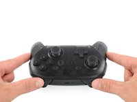
Voltea el mando para que las pegatinas de los modelos estén orientadas hacia el techo.
-
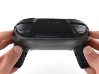
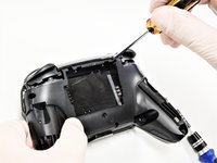
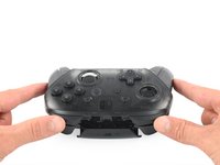
Usa un destornillador JIS#00 para quitar los dos tornillos negros de 8,4 mm que sujetan las manijas, ubicados en los extremos de las manijas.
 Pregunta a FixBot
-
-
-
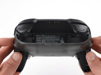
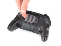
Retira con cuidado las tapas de las asas separándolas del cuerpo principal.
-
-
-
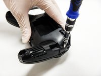
Utiliza un destornillador JIS n.º 00 para quitar los cuatro tornillos plateados de 6,8 mm que sujetan la cubierta de plástico transparente posterior.
-
-
-
Retira con cuidado la cubierta de plástico transparente con la uña.
-
-
-
Retira la cubierta de plástico transparente.
-
-
-
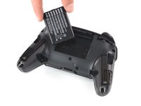
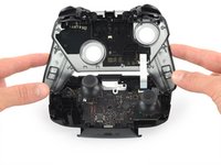
Retira la batería de iones de litio haciendo palanca con una uña o una herramienta de apertura de plástico en el lado izquierdo.
-
-
-
-
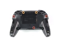
Usa un destornillador Phillips #1 para quitar los cinco tornillos de 5 mm de largo de la parte posterior del controlador.
-
Los tornillos ubicados en la parte superior de los mangos y el tornillo ubicado debajo del hueco de la batería se hallan en huecos poco profundos y pueden quitarse sin dificultad.
-
Los dos tornillos ubicados a los lados de los botones ZR y ZL se hallan en huecos bastante profundos. Necesitarás un extensor, o un destornillador Phillips lo suficientemente largo para alcanzar los tornillos.
-
-
-
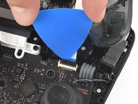
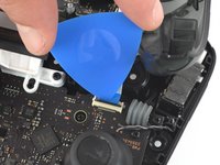
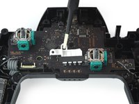
Usa la punta de una púa de apertura para abrir la solapa negra del conector ZIF empujándolo hacia arriba
-
-
Herramienta utilizada en este paso:Tweezers$4.99
-
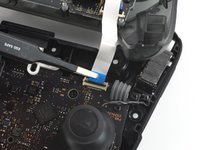
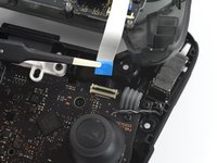
Usa tus dedos o un par de pinzas sin punta de punta roma para desconectar el cable de interconexión de su conector.
-
-
-
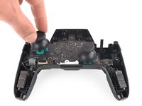
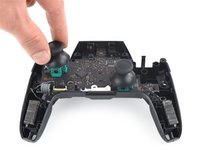
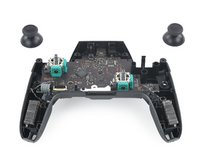
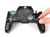
Con una fuerza ligera, extrae las dos tapas de la palanca de mando del controlador.
-
-
-
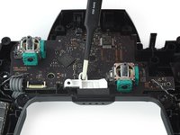
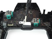
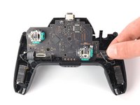
Usa un destornillador Philipps para quitar los cuatro tornillos de 5 mm de largo que sujetan la placa base.
-
-
-
Usa tu uña o un par de pinzas para sacar el LED de su ranura.
-
-
-
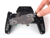
Afloja la placa de circuito del chasis tirando suavemente de la esquina inferior derecha.
-
Levanta la placa de circuito para exponer su parte trasera.
-
-
Herramienta utilizada en este paso:FixHub Smart Soldering Iron$79.95
-
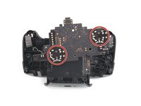
Gira hacia la parte trasera del circuito para tener acceso a las soldaduras.
-
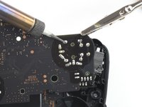
Desoldarr todas las uniones soldadas delineadas.
-
Retira el módulo de la palanca de mando de la placa de circuito.
-


Para volver a ensamblar tu dispositivo, sigue estas instrucciones en orden inverso.
Cancelar: No complete esta guía.
55 personas más completaron esta guía.
Un agradecimiento especial a estos traductores:
91%


Estos traductores nos están ayudando a reparar el mundo! ¿Quieres contribuir?
Empezar a traducir ›

Equipo

Cal Poly, Team S11-G2, Regan Fall 2019 Miembro de Cal Poly, Team S11-G2, Regan Fall 2019
CPSU-REGAN-F19S11G2
Miembros de 5
45 Guías creadas
28Guía Comentarios
I managed to replace mine with much difficulty with the soldering but the stick does not seem to turn fully anymore, both with the replacement and the original. For reference, when I go to test it, it no longer registers as reaching the outer circle when pressed all the way down. Similarly when I go to calibrate it, it only reaches up til about the 2nd outer circle, not enough to actually trigger the green arrow. Since this seems to occur on both the replacement and original stick now, I’m guessing this must be some issue that arose while I was struggling with the desoldering process. Anybody have any ideas what might be causing my issue? Have I just damaged it beyond repair?
Without pictures it is impossible to tell, but there is the possibility that you strips the metal connection on the solder point. This is fixable by “bridging” the connection. You will want to find schematics of the wiring for the PCB and then solder the wire over to the next connection.
As a side note, I should mention that I have never tried this on a controller of any sort and that I have only used this method on keyboards with single wire connections. It is possible that the connection in a controller PCB have more going on and that this technique will not work.
I have the same problem, I buy 2 joystick module from iFixit and the two gave me the same issue, the joystick module don't reach the green arrow.
I can't calibrate because of that issue.
Any ideas?
I have also had the same issue with replacement, only reaches roughly 75%. I contacted ifixit and they sent me a replacement thinking it might be a faulty pot, I installed the new stick and have the same issue. Maybe different years used different resistance.
See my answer a bit down. I think it has to do with the resistance of the module. I had the same issue with the part I received from iFixit, the original part has a resistance of 1150 ohm, but the replacement is 1600 ohm. And I have a different module which is about 500 ohm, and that works just fine.