Esta versión puede contener ediciones incorrectas. Cambie a la última instantánea verificada.
Qué necesitas
-
-
Remueve los siguientes diez tornillos que sujetan la caja inferior de la caja a la caja superior:
-
Siete tornillos Phillips de 3 mm.
-
Tres tornillos Phillips de 13.5 mm.
-
-
ComprarHerramienta utilizada en este paso:P6 Pentalobe Screwdriver 2009 15" MacBook Pro Battery$5.49
-
Retira los dos tornillos de Pentalobe de 5 puntos a lo largo del borde superior de la batería.
-
-
Este paso está sin traducir. Ayuda a traducirlo
-
Use a spudger to pry the fan connector straight up off the logic board.
-
-
Este paso está sin traducir. Ayuda a traducirlo
-
Remove the three T6 Torx screws securing the left fan to the logic board.
-
Lift the fan out of the upper case.
-
-
Este paso está sin traducir. Ayuda a traducirlo
-
Use the flat end of a spudger to disconnect the left fan connector from the logic board.
-
-
Este paso está sin traducir. Ayuda a traducirlo
-
Remove the three T6 Torx screws securing the left fan to the logic board.
-
Lift the left fan out of the upper case.
-
-
-
Este paso está sin traducir. Ayuda a traducirlo
-
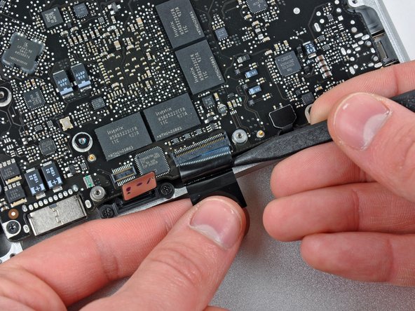
Hold the end of the cable retainer down with one finger while you use the tip of a spudger to slightly lift the other end and rotate it away from the camera cable connector.
-
Disconnect the camera cable by pulling the male end straight away from its socket.
-
-
Este paso está sin traducir. Ayuda a traducirlo
-
Disconnect the camera cable by pulling the male end straight away from its socket.
-
-
Este paso está sin traducir. Ayuda a traducirlo
-
Use the flat end of a spudger to pry the optical drive cable connector up off the logic board.
-
-
Este paso está sin traducir. Ayuda a traducirlo
-
Using the flat end of a spudger, pry the subwoofer connector straight up from the connector jack.
-
-
Este paso está sin traducir. Ayuda a traducirlo
-
Use the flat end of a spudger to pry the hard drive/IR sensor cable connector up off the logic board.
-
-
Este paso está sin traducir. Ayuda a traducirlo
-
Remove the two 1.5 mm Phillips screws securing the cable cover to the logic board.
-
Lift the cable cover out of the upper case.
-
-
Este paso está sin traducir. Ayuda a traducirlo
-
Use a spudger to pry the trackpad flex ribbon cable connector up off the logic board.
-
-
Este paso está sin traducir. Ayuda a traducirlo
-
Use your fingernail to flip up the locking flap on the ZIF socket for the keyboard ribbon cable. The locking flap is located at the opposite side of the socket compared to the keyboard ribbon cable. Hook your fingernail under it and carefully lift it up vertically.
-
Use the tip of a spudger to slide the keyboard ribbon cable out of its socket.
-
-
Este paso está sin traducir. Ayuda a traducirlo
-
Use a spudger to pry the battery indicator ribbon cable connector up off the logic board.
-
-
Este paso está sin traducir. Ayuda a traducirlo
-
Remove the single 7 mm Phillips screw securing the display data cable retainer to the upper case.
-
Remove the display data cable retainer from the upper case.
-
-
Este paso está sin traducir. Ayuda a traducirlo
-
Grab the plastic pull tab secured to the display data cable lock and rotate it toward the DC-in side of the computer.
-
-
Este paso está sin traducir. Ayuda a traducirlo
-
Pull the display data cable connector straight away from its socket.
-
-
Este paso está sin traducir. Ayuda a traducirlo
-
Using the tip of a spudger, flip up the keyboard backlight ribbon cable retaining flap.
-
Pull the keyboard backlight ribbon cable straight out of its socket.
-
-
Este paso está sin traducir. Ayuda a traducirlo
-
Remove the following screws:
-
Seven 3.3 mm T6 Torx screws securing the logic board to the upper case.
-
Two 8 mm T6 Torx screws securing the DC-In board to the upper case.
-
-
Este paso está sin traducir. Ayuda a traducirlo
-
Carefully lift the logic board assembly from the left side and work it out of the upper case, minding the port side that may get caught during removal.
-
-
Este paso está sin traducir. Ayuda a traducirlo
-
Lift the logic board enough to gain clearance and use a spudger to pry the microphone up off the upper case.
-
Slide the logic board away from the port openings and lift the assembly out of the upper case.
-
-
Este paso está sin traducir. Ayuda a traducirlo
-
Slide the logic board away from the port openings and lift the assembly out of the upper case.
-
-
Este paso está sin traducir. Ayuda a traducirlo
-
Lay the logic board down on a soft flat surface with the heat sink facing up.
-
-
Este paso está sin traducir. Ayuda a traducirlo
-
Remove the eight Phillips screws securing the heat sink to the logic board.
-
Carefully lift the heat sink off the logic board.
-
If you need to mount the heat sink back into the laptop, we have a thermal paste guide that makes replacing the thermal compound easy.
-


Cancelar: No complete esta guía.
25 personas más completaron esta guía.

3 comentarios
I did use a common flathead screwdriver for 5-point and 6-point screws. It' worked well.
Thank you very much for this guide !
I just used this guide to pull out my logic board and clean about 6 years of dust out. Also was able to take apart the fans and throw a little bit of wd40 on the axels. We are back to whisper quiet computing and about 10-15 degrees cooler.
I messed up something because the machine doesn't turn on (