Esta versión puede contener ediciones incorrectas. Cambie a la última instantánea verificada.
Qué necesitas
-
-
Usa tus dedos para empujar ambas pestañas de liberación de la batería para separarlas de la batería y levanta la batería para sacarla de la computadora.
-
-
-
Retira los tres tornillos Phillips idénticos de la tapa de la memoria.
-
-
-
Retira los dos tornillos Phillips en el compartimiento de la batería cerca del pestillo.
-
-
-
Levanta la parte posterior del estuche y pasa los dedos por los lados, liberando el estuche a medida que avanza. Una vez que hayas liberado los lados, es posible que tengas que mover la caja hacia arriba y hacia abajo para liberar el frente de la caja superior. Esta etapa puede ser bastante complicada.
-
Sobre el lector de DVD hay 4 pestañas retrasadas que se abren verticalmente.
-
Ten en cuenta que las dos pequeñas lengüetas en el frente izquierdo de la caja superior pueden doblarse mientras retiras la caja superior. Al volver a instalarlos, es posible que debas doblarlos hacia atrás para que encajen en las ranuras de la carcasa inferior.
-
-
Este paso está sin traducir. Ayuda a traducirlo
-
Disconnect the two antenna cables attached to the Airport Extreme card.
-
-
Este paso está sin traducir. Ayuda a traducirlo
-
Deroute the Airport antenna cables from their channel in the left speaker.
-
-
Este paso está sin traducir. Ayuda a traducirlo
-
Disconnect the iSight, inverter, and left fan cables from the logic board by gently pulling in the direction of each cable.
-
-
Este paso está sin traducir. Ayuda a traducirlo
-
Disconnect the display data cable from the logic board.
-
-
-
Este paso está sin traducir. Ayuda a traducirlo
-
Remove the silver T6 Torx screw securing the ground loop on the display data cable to the casing.
-
-
Este paso está sin traducir. Ayuda a traducirlo
-
Support the display with one hand while removing the following 3 screws:
-
Two 9.5 mm silver T6 Torx screws with threads on only part of the shaft on the inside of the display hinges.
-
One 9.5 mm silver T6 Torx screw with threads on the entire shaft on the outside of the left hinge.
-
-
Este paso está sin traducir. Ayuda a traducirlo
-
Grasp the display assembly on both sides and lift it up and out of the computer.
-
-
Este paso está sin traducir. Ayuda a traducirlo
-
Remove the two 5 mm Phillips screws from the lower left and right corners of the display (two screws total).
-
-
Este paso está sin traducir. Ayuda a traducirlo
-
Insert the flat end of a spudger perpendicular to the face of the display between the plastic strip attached to the rear bezel and the front bezel.
-
With the spudger still inserted, rotate it away from the display to separate the front and rear bezels.
-
Work along the left edge of the display until the rear bezel is evenly separated from the front bezel.
-
-
Este paso está sin traducir. Ayuda a traducirlo
-
Insert the flat end of a spudger perpendicular to the face of the display between the plastic strip attached to the rear bezel and the front bezel.
-
With the spudger still inserted, rotate it away from the display to separate the front and rear bezels.
-
Work along the right edge of the display until the rear bezel is evenly separated from the front bezel.
-
-
Este paso está sin traducir. Ayuda a traducirlo
-
Insert the flat end of a spudger between the front bezel and the plastic strip attached to the rear bezel near the screw holes at the bottom corners of the display.
-
Rotate your spudger toward the rear bezel to separate it from the front bezel.
-
If necessary, enlarge the gap between the lower edge of the rear bezel and the clutch cover until the two components are completely separated.
-
-
Este paso está sin traducir. Ayuda a traducirlo
-
Lift the rear bezel by its bottom edge and rotate it away from the display assembly to separate the top edge.
-
Remove the rear display bezel from the display assembly.
-
-
Este paso está sin traducir. Ayuda a traducirlo
-
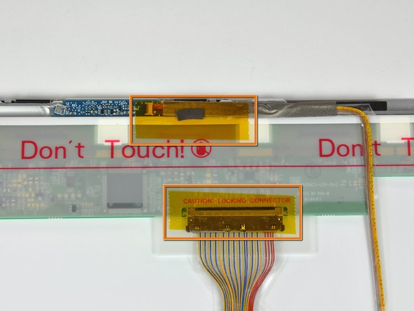
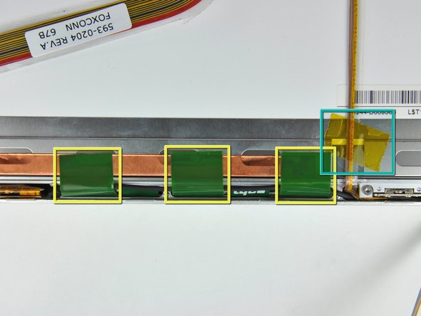
Remove the pieces of yellow kapton tape from the bottom left corner of the display.
-
Remove the pieces of tape securing the display data cable and camera cable to the display.
-
Peel the three green antenna ground straps off the copper tape along the bottom edge of the LCD.
-
Remove the piece of tape securing the camera cable to the LCD.
-
-
Este paso está sin traducir. Ayuda a traducirlo
-
Carefully peel the camera cable off the foam tape along the top edge of the LCD.
-
-
Este paso está sin traducir. Ayuda a traducirlo
-
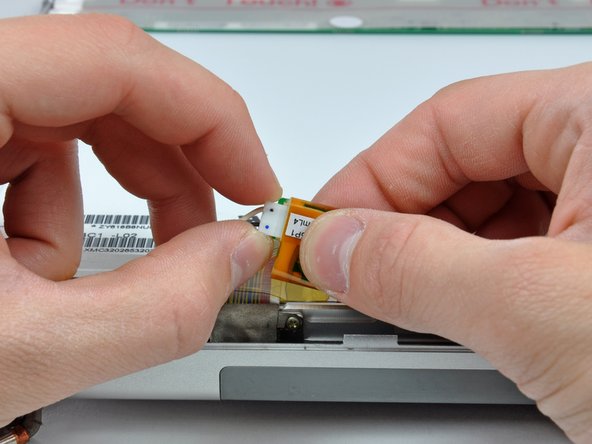
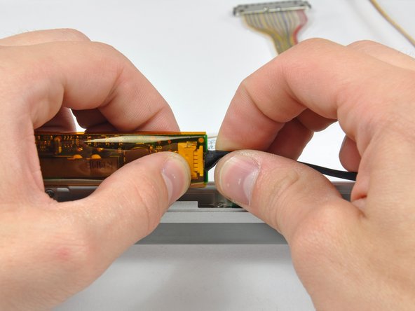
Use the tip of a spudger and carefully flip the ZIF connector bar up to release the before the camera cable.
-
Gently pull the camera cable away from its socket on the camera board.
-
-
Este paso está sin traducir. Ayuda a traducirlo
-
Pull the display data cable connector away from its socket on the LCD.
-
-
Este paso está sin traducir. Ayuda a traducirlo
-
Remove the four black Phillips screws along the left and right edges of the display (eight screws total).
-
-
Este paso está sin traducir. Ayuda a traducirlo
-
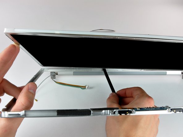
Use the flat end of a spudger to gently lift one of the top corners of the LCD out of the front bezel.
-
-
Este paso está sin traducir. Ayuda a traducirlo
-
Work your way along the top edge of the LCD, slowly prying the attached steel strip away from the front bezel.
-
-
Este paso está sin traducir. Ayuda a traducirlo
-
Now that the top edge is free, slightly lift the LCD out of the front bezel for enough room to pry the steel strip along the lower edge of the LCD away from the front bezel.
-
Pry along the lower edge of the LCD until it is freed from the adhesive on the front bezel.
-
-
Este paso está sin traducir. Ayuda a traducirlo
-
Lift the inverter out of the clutch cover.
-
Disconnect the LCD backlight connector from its socket on the inverter board.
-
-
Este paso está sin traducir. Ayuda a traducirlo
-
Lift the LCD out of the front bezel, minding any cables that may get caught.
-
-
Este paso está sin traducir. Ayuda a traducirlo
-
Lift the inverter out of the clutch cover.
-
Disconnect the inverter cable from the inverter by pulling its cable away from the socket on the inverter board.
-
Remove the inverter and set it aside.
-
-
Este paso está sin traducir. Ayuda a traducirlo
-
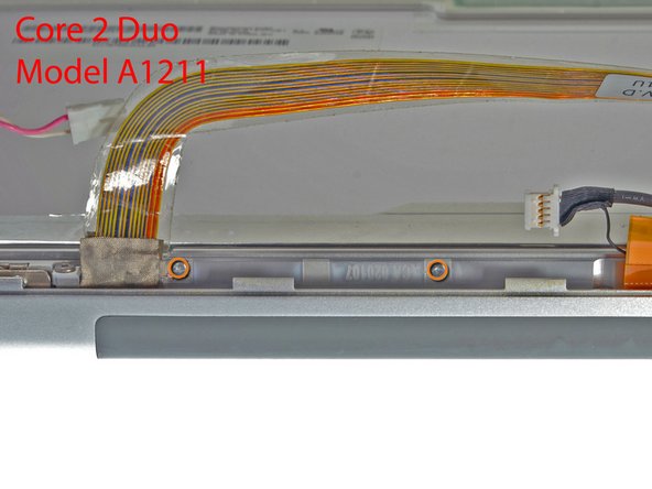
If you have a Core Duo machine, refer to picture 1 and remove three Phillips screws connecting the clutch assembly to the lower edge of the front display bezel near the display data cable.
-
If you have a Core 2 Duo Model A1211 machine, refer to picture 2 and remove two Phillips screws connecting the clutch assembly to the lower edge of the front display bezel near the display data cable.
-
-
Este paso está sin traducir. Ayuda a traducirlo
-
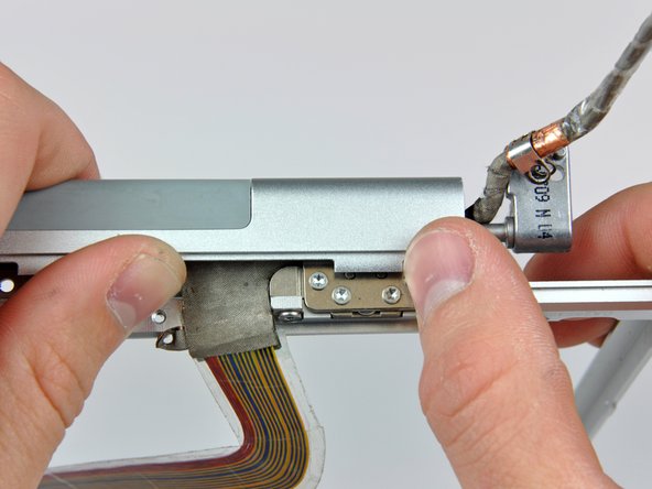
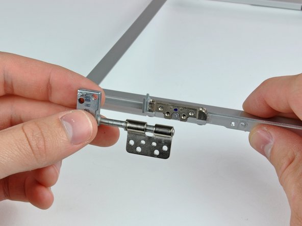
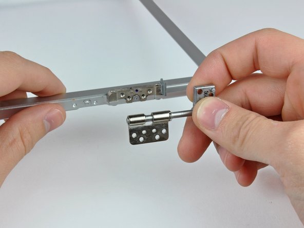
Remove the single black Phillips screw from behind the display data cable.
-
Slide the small steel bracket away from the right clutch hinge and remove it from the clutch assembly.
-
-
Este paso está sin traducir. Ayuda a traducirlo
-
Remove the three Phillips screws along the inside of the clutch cover near the inverter/camera cable.
-
-
Este paso está sin traducir. Ayuda a traducirlo
-
Push the open edge of the clutch cover away from the left clutch hinge to pop it off the clips attaching the two parts.
-
If necessary, repeat this process for the right side of the clutch assembly.
-
Remove the clutch assembly from the front display bezel.
-
-
Este paso está sin traducir. Ayuda a traducirlo
-
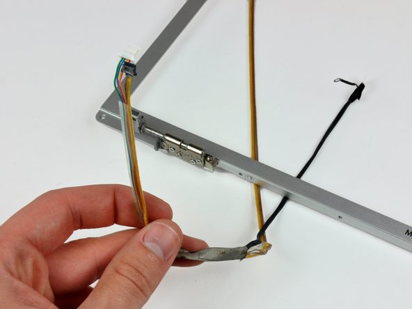
De-route the display data and inverter/camera cables around the clutch hinges and remove both cables.
-
-
Este paso está sin traducir. Ayuda a traducirlo
-
Remove the four T6 Torx screws securing the left clutch hinge to the front display bezel.
-
Remove the left clutch hinge and set it aside.
-
-
Este paso está sin traducir. Ayuda a traducirlo
-
Remove the four T6 Torx screws securing the right clutch hinge to the front display bezel.
-
Remove the right clutch hinge and set it aside.
-


Cancelar: No complete esta guía.
6 personas más completaron esta guía.
