Saltar al contenido principal

Esta traducción podría no reflejar los cambios más recientes añadidos a la guía de referencia. Ayúdanos a actualizar la traducción o revisa la guía original.

Qué necesitas

  1. , Batería: paso 1, imagen 1 de 1
    • Utiliza una moneda o un spudger para girar el tornillo de bloqueo de la batería 90 grados en el sentido de las agujas del reloj.

  2. : paso 2, imagen 1 de 1
    • Extrae la batería del ordenador.

  3. , Cubierta de la memoria: paso 3, imagen 1 de 1
    • Retira los tres tornillos Phillips espaciados uniformemente a lo largo de la pared posterior del compartimento de la batería.

    • Los tornillos están fijados a la cubierta metálica de la memoria.

    • Cuando vuelvas a colocar la carcasa de la batería, utiliza un spudger para volver a insertar el acolchado de espuma detrás de la pared trasera para espaciar mejor la batería.

  4. : paso 4, imagen 1 de 1
    • Levanta la tapa de la memoria en forma de L, deslízala hacia la derecha y retírala del ordenador.

  5. Este paso está sin traducir. Ayuda a traducirlo

    : paso 5, imagen 1 de 1
    • Remove the following 3 screws:

    • One 11 mm Phillips #00 in the middle of the case.

    • Two 14.5 mm Phillips #00.

    • If the screws stick in the case, you can use a magnetized screwdriver to draw them out.

    • The shorter of the three screws goes in the middle.

  6. Este paso está sin traducir. Ayuda a traducirlo

    : paso 6, imagen 1 de 1
    • Remove the following 3 screws from the rear wall of the battery compartment:

    • Two 3 mm Phillips #00. (A1181 has three 3 mm screws and one 4 mm.)

    • One 4 mm Phillips #00 on the right side.

    • When reinstalling these screws, press gently on the lower case to line up the screw holes.

    • These screws easily strip, so be careful while taking these particular screws out.

  7. Este paso está sin traducir. Ayuda a traducirlo

    : paso 7, imagen 1 de 1
    • Remove the two 6 mm Phillips #00 screws from either side of the right wall of the battery compartment (not the ones closest to the battery connector).

  8. Este paso está sin traducir. Ayuda a traducirlo

    : paso 8, imagen 1 de 1
    • Remove the four 3 mm indicated Phillips #00 screws from the front wall of the battery compartment. When working from the left, remove the 2nd, 4th, 7th and 9th screw.

  9. Este paso está sin traducir. Ayuda a traducirlo

    : paso 9, imagen 1 de 1
    • Remove the following 4 screws from the back of the computer:

    • Two 7 mm shouldered Phillips on the far sides.

    • Two 10.5 mm Phillips toward the center.

    • Do not over-tighten these; you can cause the case to distort.

  10. Este paso está sin traducir. Ayuda a traducirlo

    : paso 10, imagen 1 de 1
    • Remove the two 5.2 mm shouldered Phillips #00 screws from the optical side of the computer.

    • It is not necessary to remove the similar screws on the other side of the computer.

  11. Este paso está sin traducir. Ayuda a traducirlo

    : paso 11, imagen 1 de 1
    • Starting near the display and working around to the front of the computer, pry up on the upper case. It is held with clips on the right above the optical drive. These will release with some firm lifting pressure.

    • Be careful when prying up the upper case. It's very easy to slice open a fingertip and thus provide the blood sacrifice the Mac gods sometimes require of those who insist on doing their own repairs.

    • There's a trackpad and keyboard ribbon connecting the upper case to the logic board, so don't pull the upper case off entirely just yet.

    • If you have trouble getting the clips to release, be careful that you are not prying the plastic top of the upper case away from its metal frame.

  12. Este paso está sin traducir. Ayuda a traducirlo

    : paso 12, imagen 1 de 1
    • While holding up the upper case (from the bottom or the top), use a spudger to pry up the orange trackpad and keyboard cable from its connector.

    • Take care to pry between the black socket and the white connector. You might have to pry on both sides for it to release properly.

    • Do not pry from the bottom or the top, but from the sides.

    • If you happen to break your upper case cable when removing the upper case, we stock the cable individually and we have a guide that makes replacing it easy.

  13. : paso 13, imagen 1 de 1
    • Si tienes un cable de caja superior plateada, salta al paso 22.

    • Si tienes un cable de carcasa superior marrón, sigue este y los siguientes pasos para reemplazar el cable de carcasa superior.

    • Retire con cuidado el cable de la carcasa superior del adhesivo que lo sujeta a la carcasa superior.

  14. : paso 14, imagen 1 de 2 : paso 14, imagen 2 de 2
    • Usa el extremo plano de un spudger para despegar con cuidado el adhesivo alrededor del perímetro del panel de plástico pegado a la parte inferior del trackpad.

    • Retira el panel de la carcasa superior.

  15. : paso 15, imagen 1 de 2 : paso 15, imagen 2 de 2
    • Usa la punta de un spudger o la uña para levantar la solapa de retención en el conector ZIF del cable de la carcasa superior cerca del cable del teclado.

    • Asegúrate de que estás haciendo palanca en la solapa de retención, no en el propio zócalo.

  16. : paso 16, imagen 1 de 1
    • Despega con cuidado la sección del cable de la carcasa superior adherida al cable plano del teclado, teniendo cuidado de no alterar el cable plano del teclado en el proceso.

  17. : paso 17, imagen 1 de 1
    • Extrae el conector del cable plano de la carcasa superior superior de su zócalo debajo del panel táctil.

  18. : paso 18, imagen 1 de 2 : paso 18, imagen 2 de 2
    • Usa la punta de un spudger para levantar la solapa de retención en el conector del cable plano del botón del mouse.

    • Asegúrate de hacer palanca en la solapa de retención, no en el zócalo en sí.

  19. : paso 19, imagen 1 de 1
    • Tira del cable plano del botón del mouse para sacarlo de su zócalo.

  20. : paso 20, imagen 1 de 1
    • Usa el extremo plano de un spudger para ayudar a despegar la última parte del cable plano de la carcasa superior del adhesivo que lo sujeta a la parte inferior del trackpad.

  21. : paso 21, imagen 1 de 1
    • Retira el cable de la carcasa superior de la carcasa superior.

  22. Este paso está sin traducir. Ayuda a traducirlo

    : paso 22, imagen 1 de 2 : paso 22, imagen 2 de 2
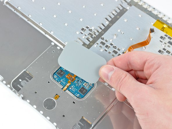
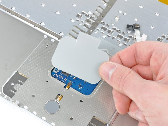
    • Use the flat end of a spudger to carefully peel up the adhesive around the perimeter of the plastic panel stuck to the underside of the trackpad.

    • Remove the panel from the upper case.

  23. Este paso está sin traducir. Ayuda a traducirlo

    : paso 23, imagen 1 de 1
    • Carefully peel the upper case cable and the piece of clear tape off the bottom of the upper case.

  24. Este paso está sin traducir. Ayuda a traducirlo

    : paso 24, imagen 1 de 2 : paso 24, imagen 2 de 2
    • Use the tip of a spudger to flip up the retaining flap on the upper case cable ZIF socket.

    • Be sure you are prying up on the hinged retaining flap, not the socket itself.

  25. Este paso está sin traducir. Ayuda a traducirlo

    : paso 25, imagen 1 de 1
    • Pull the upper case cable out of its socket and remove it from the upper case.

Linea de Meta

33 personas más completaron esta guía.

Un agradecimiento especial a estos traductores:

en es

52%

Estos traductores nos están ayudando a reparar el mundo! ¿Quieres contribuir?
Empezar a traducir ›

Un comentario

Andrew you are the best.Very easy to follow instructions.I will replace mind,90 points

Mosua Patrick - Contestar

Agregar Comentario

Ver Estadísticas:

Ultimas 24 horas: 1

Ultimos 7 días: 9

Ultimos 30 días: 41

Todo El Tiempo: 23,630