Esta versión puede contener ediciones incorrectas. Cambie a la última instantánea verificada.
Introducción
Use esta guía para reemplazar el ensamblaje de la pantalla de su MacBook Air.
Qué necesitas
-
ComprarHerramienta utilizada en este paso:P5 Pentalobe Screwdriver Retina MacBook Pro and Air$5.99
-
Retira los siguientes diez tornillos:
-
Dos tornillos Pentalobe de 9 mm y 5 puntos
-
Ocho tornillos Pentalobe de 2,6 mm y 5 puntos
-
-
-
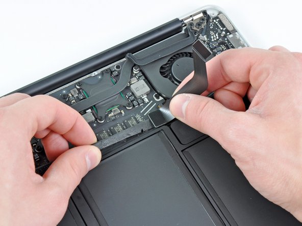
Este paso es opcional y no es obligatorio. Tome la lengüeta de plástico transparente que está unida al conector de la batería y tire de ella hacia el borde delantero del aire para desconectar la batería de la placa lógica.
-
-
Este paso está sin traducir. Ayuda a traducirlo
-
Use the flat end of a spudger to pry the I/O board cable connector upward out of its socket on the I/O board.
-
-
Este paso está sin traducir. Ayuda a traducirlo
-
Carefully peel the I/O board cable from the top of the fan.
-
While gently pulling the I/O board cable upward near its connection to the logic board, use the tip of a spudger to pry upward on alternating sides of the connector to help "walk" it out of its socket.
-
Remove the I/O board cable.
-
-
-
Use la punta de un spudger para levantar con cuidado la aleta de retención del zócalo ZIF del cable del ventilador.
-
-
Este paso está sin traducir. Ayuda a traducirlo
-
Disconnect the I/O board by pulling the power cable away from its socket on the logic board.
-
-
Este paso está sin traducir. Ayuda a traducirlo
-
Pull the camera cable parallel to the face of the I/O board toward the corner of the Air to disconnect it from its socket, using the tip of a spudger to help push the connector out of its socket.
-
-
Este paso está sin traducir. Ayuda a traducirlo
-
Use the flat end of a spudger to pry the left speaker cable connector up and out of its socket on the I/O board.
-
De-route the left speaker cable from its retainer on the I/O board.
-
-
-
Este paso está sin traducir. Ayuda a traducirlo
-
Use the flat end of a spudger to pry the microphone cable connector up and out of its socket on the I/O board.
-
-
Este paso está sin traducir. Ayuda a traducirlo
-
Remove the single 3.6 mm T5 Torx screw securing the I/O board to the upper case.
-
-
Este paso está sin traducir. Ayuda a traducirlo
-
Carefully lift the I/O board from its edge nearest the logic board and remove it from the upper case.
-
-
Este paso está sin traducir. Ayuda a traducirlo
-
Remove the following five screws securing the battery to the upper case:
-
Three 6.3 mm T5 Torx screws
-
Two 2.4 mm T5 Torx screws
-
-
Este paso está sin traducir. Ayuda a traducirlo
-
Lift the battery from its edge nearest the logic board and remove it from the upper case.
-
-
Este paso está sin traducir. Ayuda a traducirlo
-
Use the tip of a spudger or your fingernail to flip up the retaining flap on the trackpad ribbon cable ZIF socket.
-
Pull the trackpad ribbon cable straight out of its socket toward the front edge of the Air.
-
-
Este paso está sin traducir. Ayuda a traducirlo
-
Use the flat end of a spudger to pry the right speaker cable connector up and out of its socket on the logic board.
-
-
Este paso está sin traducir. Ayuda a traducirlo
-
Gently push the tip of a spudger under the black plastic flap stuck to the display data cable lock to make the lock pop upward and away from the socket.
-
While holding the lock away from the socket, use the tip of a spudger and your fingers to gently remove the display data cable from its socket by sliding it toward the corner of the Air.
-
-
Este paso está sin traducir. Ayuda a traducirlo
-
Use the flat end of a spudger to pry both antenna cable connectors up and off their sockets on the AirPort/Bluetooth card.
-
-
Este paso está sin traducir. Ayuda a traducirlo
-
Gently de-route the antenna cables from the slot cut into the logic board.
-
-
Este paso está sin traducir. Ayuda a traducirlo
-
Remove the single 2.85 mm T5 Torx screw securing the SSD to the logic board.
-
-
Este paso está sin traducir. Ayuda a traducirlo
-
Pull the drive straight out of its socket and remove it from the logic board.
-
-
Este paso está sin traducir. Ayuda a traducirlo
-
Remove the six 6.3 mm T5 Torx screws securing the logic board to the upper case.
-
-
Este paso está sin traducir. Ayuda a traducirlo
-
Remove the inner two 4.9 mm T8 Torx screws securing the antenna cable retainer and left clutch hinge to the upper case.
-
-
Este paso está sin traducir. Ayuda a traducirlo
-
Push the antenna cable retainer away slightly and remove the 3 mm T5 Torx screw securing the end of the heat sink to the upper case.
-
-
Este paso está sin traducir. Ayuda a traducirlo
-
Carefully remove the logic board assembly from the upper case, minding any cables that may get caught.
-
-
-
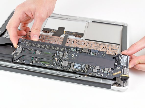
Desencade suavemente los cables de la antena del corte del canal en la carcasa superior.
-
-
-
Empuje la carcasa superior ligeramente hacia el conjunto de la pantalla, luego gírela hacia afuera desde el frente del ensamblaje de la pantalla.
-
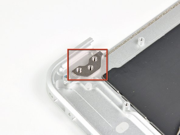
Una vez que las dos bisagras de la pantalla han despejado la carcasa superior, retire la pantalla y déjela a un lado. Mantenga un registro de las cuñas debajo de cada uno de los dos soportes de visualización.
-


Para volver a armar su dispositivo, siga estas instrucciones en orden inverso.
Para volver a armar su dispositivo, siga estas instrucciones en orden inverso.
Cancelar: No complete esta guía.
71 personas más completaron esta guía.
Un agradecimiento especial a estos traductores:
100%

¡ irlanda nos está ayudando a reparar el mundo! ¿Quieres contribuir?
Empezar a traducir ›

12 comentarios
Removing the logic board is completely unnecessary and you risk damaging more components. Follow steps 1-3, 11, 20-22, 26, 30-34. Obviously be careful not to damage the board when you are actually taking the display off.
Beau is correct . It isn't necessary at all to remove the logic board. Steps 1-3, 11, 20-22, 26, 30-34 are all that needs to be done.
Excellent guide, however, I would like to note that removing the logic board is completely unnecessary. In the process of doing so, I ended up breaking my right speaker socket from the logic board. The simpler method is to just unscrew the display hinge, antenna, and isight cable, then remove and replace display.