Esta versión puede contener ediciones incorrectas. Cambie a la última instantánea verificada.
Qué necesitas
-
-
Retira los siguientes 10 tornillos:
-
Dos tornillos Pentalobe de 5 Puntos de 8 mm
-
Ocho tornillos Pentalobe de 5 Puntos de 2.5 mm
-
-
-
Usa el extremo plano de un spudger para levantar ambos lados cortos del conector de la batería hacia arriba para desconectarlo de su zócalo en la placa lógica.
-
Dobla el cable de la batería un poco lejos de la placa lógica para que el conector no se doble hacia atrás accidentalmente y haga contacto con su zócalo.
-
-
-
Utiliza el extremo plano de un spudger para hacer palanca en los conectores de cable izquierdo y derecho de la placa de E/S para sacarlos de sus respectivos zócalos en la placa de E/S.
-
-
Este paso está sin traducir. Ayuda a traducirlo
-
Use the tip of a spudger to carefully push on each side of the iSight camera cable connector to loosen it out of its socket on the logic board.
-
-
Este paso está sin traducir. Ayuda a traducirlo
-
Peel the iSight camera cable up off the adhesive securing it to the fan.
-
-
Este paso está sin traducir. Ayuda a traducirlo
-
Use the tip of a spudger to carefully flip up the retaining flap on the fan cable ZIF socket.
-
-
Este paso está sin traducir. Ayuda a traducirlo
-
Remove the following three screws securing the fan to the upper case:
-
Two 5.5 mm T5 Torx screws
-
One 4.6 mm T5 Torx screw
-
-
-
Este paso está sin traducir. Ayuda a traducirlo
-
Lift, but do not remove the fan out of its recess in the upper case.
-
Carefully pull the fan ribbon cable out of its socket as you remove the fan from the Air.
-
-
Este paso está sin traducir. Ayuda a traducirlo
-
Use the flat end of a spudger to pry both antenna connectors up from their sockets on the AirPort/Bluetooth card, and move them out of the way.
-
-
Este paso está sin traducir. Ayuda a traducirlo
-
Remove the following five screws securing the battery to the upper case:
-
Two 5.2 mm T5 Torx screws
-
One 6 mm T5 Torx screw
-
Two 2.6 mm T5 Torx screws
-
-
Este paso está sin traducir. Ayuda a traducirlo
-
Lift the battery from its edge nearest the logic board and remove it from the upper case.
-
-
Este paso está sin traducir. Ayuda a traducirlo
-
Disconnect the I/O board by pulling the power cable away from its socket on the logic board.
-
-
Este paso está sin traducir. Ayuda a traducirlo
-
Use the tip of a spudger to de-route the antenna cables from their notches in the logic board.
-
-
Este paso está sin traducir. Ayuda a traducirlo
-
Gently push the tip of a spudger under the black plastic flap stuck to the display data cable lock to make the lock pop upward and away from the socket.
-
While holding the lock away from the socket, gently pull the display data cable out of its socket.
-
-
Este paso está sin traducir. Ayuda a traducirlo
-
Use the tip of a spudger to pry under the speaker cable connector, lifting it straight up from its socket.
-
De-route the cable from its notch in the logic board.
-
-
Este paso está sin traducir. Ayuda a traducirlo
-
Use the tip of a spudger or your fingernail to flip up the retaining flap on the trackpad ribbon cable ZIF socket.
-
Pull the trackpad ribbon cable straight out of its socket toward the front edge of the Air.
-
-
Este paso está sin traducir. Ayuda a traducirlo
-
Use the tip of a spudger to flip up the retaining flap on the keyboard backlight ribbon cable ZIF socket.
-
Pull the keyboard backlight ribbon cable out of its socket.
-
-
Este paso está sin traducir. Ayuda a traducirlo
-
Remove the single 2.9 mm T5 Torx screw securing the AirPort/Bluetooth card to the logic board.
-
-
Este paso está sin traducir. Ayuda a traducirlo
-
Slightly lift the free end of the AirPort/Bluetooth board and pull it out of its socket on the logic board.
-
-
Este paso está sin traducir. Ayuda a traducirlo
-
Remove the three 3.6 mm T5 Torx screws securing the logic board to the upper case.
-
In some models these are 3.1 mm T5 Torx screws.
-
-
Este paso está sin traducir. Ayuda a traducirlo
-
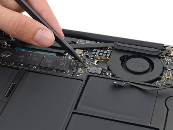
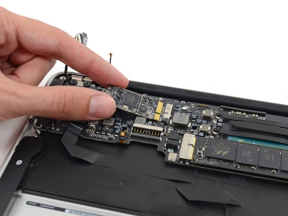
Gently lift the logic board assembly from the heat sink end and pull it away from the port side of the case to remove it from the Air.
-
-
Este paso está sin traducir. Ayuda a traducirlo
-
Remove the four 2.5 mm T5 Torx screws securing the heat sink to the logic board.
-
-
Este paso está sin traducir. Ayuda a traducirlo
-
If the heat sink seems to be stuck to the logic board after removing all four screws, use a spudger to carefully separate the heat sink from the faces of the CPU.
-
Remove the heat sink from the logic board.
-
When reinstalling the heat sink, be sure to apply a new layer of thermal paste. If you have never applied thermal paste before, we have a guide that makes it easy.
-
-
Este paso está sin traducir. Ayuda a traducirlo
-
Remove the single 2.9 mm T5 Torx screw securing the SSD to the logic board.
-
-
Este paso está sin traducir. Ayuda a traducirlo
-
Lift the free end of the SSD just enough to get a good hold of it.
-
Pull the drive straight out of its socket and remove it from the logic board.
-


Cancelar: No complete esta guía.
15 personas más completaron esta guía.


3 comentarios
Where can one order a Logic board?