Esta versión puede contener ediciones incorrectas. Cambie a la última instantánea verificada.
Qué necesitas
-
Este paso está sin traducir. Ayuda a traducirlo
-
Remove eight M2.5 x 8mm Phillips head screws, using a Phillips #0 screwdriver, in the specified locations.
-
Lift the bottom cover off and set it aside.
-
-
Este paso está sin traducir. Ayuda a traducirlo
-
Remove the two M2.5x4mm screws using a Phillips #0 screwdriver.
-
Slide the hard drive out of the casing.
-
-
Este paso está sin traducir. Ayuda a traducirlo
-
With the laptop's bottom facing up, pull the optical drive release lever back and pull the optical drive out.
-
Unscrew the three M2x3mm Phillips head screws shown.
-
At the front edge of the laptop, empty the SD card holder by pressing on the card. This will allow for further disassembly in later steps.
-
-
Este paso está sin traducir. Ayuda a traducirlo
-
Remove the two M2.5 x 6mm screws using a Phillips #00 screwdriver.
-
Disconnect the two WiFi antenna cables.
-
Disconnect the sound connector.
-
-
-
Este paso está sin traducir. Ayuda a traducirlo
-
Open the laptop hinge. Tip the laptop onto its side, and use the back end of the screwdriver to push the keyboard out from the optical drive area.
-
Turn the laptop right side up and pry the keyboard up slowly, until it is clear of the case.
-
Detach the ribbon cables by opening the specified latches.
-
-
Este paso está sin traducir. Ayuda a traducirlo
-
Detach the ribbon cables by opening the specified latches.
-
Turn the laptop upside down and remove the M2.5x8mm screw with Phillips #0 screwdriver.
-
Turn the laptop on its side and pry the bottom from the top.
-
Remove the ribbon cable by opening its respective latch.
-
-
Este paso está sin traducir. Ayuda a traducirlo
-
Remove the specified cable on top of the motherboard.
-
Flip the laptop over, and remove the specified cables.
-
Remove the two M2.5x4mm screws with a Phillips #0 screwdriver
-
Remove the motherboard with hands.
-
-
Este paso está sin traducir. Ayuda a traducirlo
-
Detach the LCD assembly by unscrewing four M2.5x4mm Phillips Screws. (Two on each side).
-
Pull the LCD assembly away from main frame.
-
-
Este paso está sin traducir. Ayuda a traducirlo
-
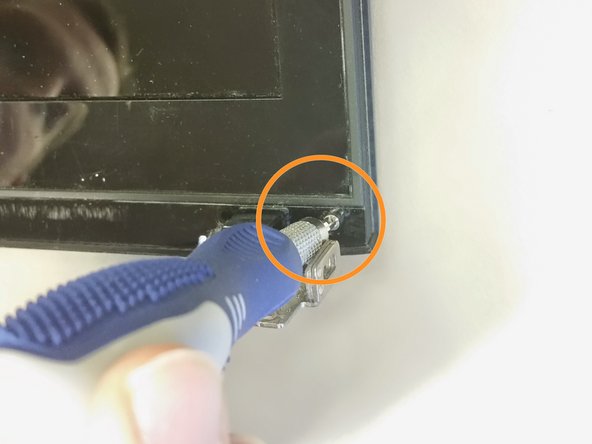
Using a flat head screwdriver, wedge out two plastic tabs to reveal the screws.
-
One tab is in the bottom left corner and one is in the bottom right corner. Symmetrical locations.
-
Using a #0 phillips screwdriver, unscrew two silver M2.5x4mm screws.
-
These are located underneath the previously removed plastic tabs.
-
-
Este paso está sin traducir. Ayuda a traducirlo
-
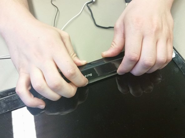
Unclip the latches at each bottom corner. They are located below the screws that were previously removed.
-
Place your fingers inside of the edge of the bezel. Separate the bezel by pulling it away from the back cover. Pull until one side has been lifted.
-
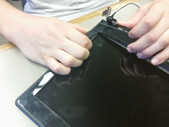
Use the same technique to separate all remaining sides of the bezel.
-
Starting at one corner and making your way around. Ensure the bezel is completely removed from the back cover.
-
Completely remove bezel from LCD screen and back cover.
-
-
Este paso está sin traducir. Ayuda a traducirlo
-
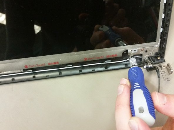
Unscrew the four M2.5x4mm Phillips screws. One screw is located at each corner.
-
-
Este paso está sin traducir. Ayuda a traducirlo
-
Gently lift the LCD screen and flip it over.
-
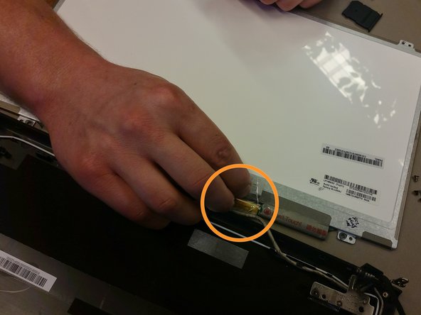
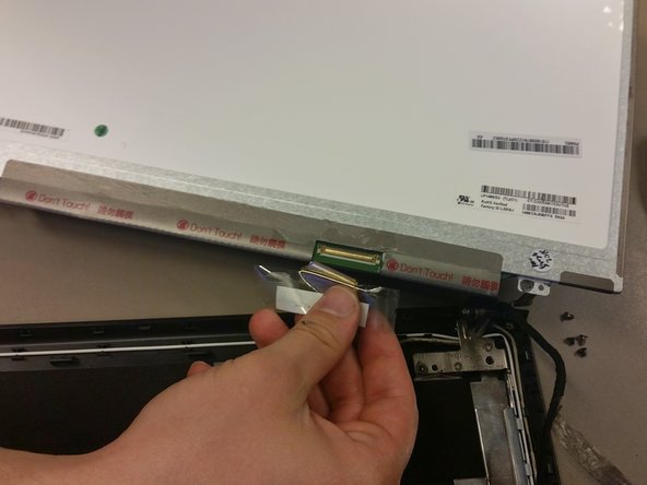
On back of the LCD screen, locate the protective tape in the bottom right corner. Peel off the tape to reveal a latch with a connector cable.
-
Flip the latch so that the connector cable can be removed. Remove the connector cable by pulling downwards.
-
The old LCD is now completely disconnected and you are ready to install a new LCD screen.
-


Cancelar: No complete esta guía.
8 personas más completaron esta guía.
Equipo

Cal Poly, Team 21-21, Maness Winter 2015 Miembro de Cal Poly, Team 21-21, Maness Winter 2015
CPSU-MANESS-W15S21G21
4 Miembros
6 Guías creadas