Esta versión puede contener ediciones incorrectas. Cambie a la última instantánea verificada.
Qué necesitas
-
Este paso está sin traducir. Ayuda a traducirlo
-
Unplug and remove the power cord. Turn the boombox upside down.
-
Grip the sides of the case and use your thumbs to pop open the battery cover.
-
-
Este paso está sin traducir. Ayuda a traducirlo
-
Turn the boombox upside down again. With the Phillips PH1 or the Flathead #3 screwdriver, remove the three 14mm black screws.
-
Remove the four 18mm chrome screws with the Phillips PH1 screwdriver.
-
-
Este paso está sin traducir. Ayuda a traducirlo
-
Gently remove the bottom half of the casing from the top half of the casing.
-
-
-
Este paso está sin traducir. Ayuda a traducirlo
-
Remove the 10mm chrome screw from the antenna base with the Phillips PH1 screwdriver. Remove the antenna base from the casing.
-
This red wire will now be loose and you can move it out of the antenna base slot.
-
-
Este paso está sin traducir. Ayuda a traducirlo
-
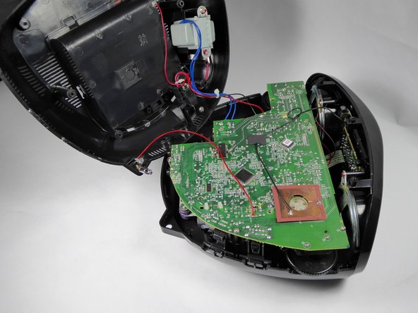
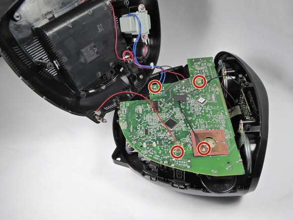
Unscrew the four 12.5mm screws with the Phillips PH1 Screwdriver.
-
Unscrew the one 10mm long screw with the Phillips PH1 Screwdriver.
-
-
Este paso está sin traducir. Ayuda a traducirlo
-
Orient the device so that the back is facing you.
-
Unplug the six pin male/female header from its socket on the motherboard. The wires on the header are these colors: burgundy, red, orange, yellow, green, and blue.
-
Gently pull out the ribbon cable from its socket on the motherboard.
-
-
Este paso está sin traducir. Ayuda a traducirlo
-
Rotate the device so that the front is facing you.
-
Unplug the four pin header from its socket on the motherboard. The wires on the header are these colors: brown, red, orange, and yellow.
-
Gently pull out the ribbon cable from its socket.
-
-
Este paso está sin traducir. Ayuda a traducirlo
-
Pull out the two pin header from its socket on the motherboard. The wires on this header are black and white.
-
-
Este paso está sin traducir. Ayuda a traducirlo
-
Scrape off the glue from the black wire with the blue plastic opening tool.
-
-
Este paso está sin traducir. Ayuda a traducirlo
-
Desolder the one black, one red, and two blue wires. If you need help soldering, see this guide.
-


Equipo

UC Davis, Team 1-5, Oliver Fall 2016 Miembro de UC Davis, Team 1-5, Oliver Fall 2016
UCD-OLIVER-F16S1G5
5 Miembros
11 Guías creadas