Esta versión puede contener ediciones incorrectas. Cambie a la última instantánea verificada.
Qué necesitas
-
Este paso está sin traducir. Ayuda a traducirlo
-
Use the plastic opening tool to remove the gray rubber pads on the bottom of the laptop. For our device we only needed to remove the two at the top.
-
-
Este paso está sin traducir. Ayuda a traducirlo
-
Use a Torx T5 screwdriver to remove the six 5.1 mm screws.
-
Use a JIS #1 screwdriver to remove the two 7.2mm screws.
-
-
Este paso está sin traducir. Ayuda a traducirlo
-
Use a plastic opening tool to pry open the case. Go slowly around the edge. You will hear popping noises, such are due to popping open the small joints that keep the cover attached.
-
-
Este paso está sin traducir. Ayuda a traducirlo
-
Use a JIS #1 screwdriver to remove the six 4.7 mm screws.
-
-
-
Este paso está sin traducir. Ayuda a traducirlo
-
Use tweezers to disconnect the battery from the motherboard.
-
-
Este paso está sin traducir. Ayuda a traducirlo
-
Use the plastic opening tool to disconnect the power cable from the fan.
-
-
Este paso está sin traducir. Ayuda a traducirlo
-
Use your fingers to lightly pull the cable and disconnect it from the motherboard.
-
-
Este paso está sin traducir. Ayuda a traducirlo
-
Use a Phillips #0 screwdriver to loosen the four 6.5 mm screws.
-
Use a JIS #1 screwdriver to remove the two 7.7 mm screws.
-
-
Este paso está sin traducir. Ayuda a traducirlo
-
Use a JIS #1 screwdriver to remove the 4.7mm screws from the indicated positions.
-
Use the JIS #1 screwdriver to remove the 7.7mm screws from the indicated positions.
-
Use the JIS #1 screwdriver to remove the 4.4mm screws from the indicated positions.
-
-
Este paso está sin traducir. Ayuda a traducirlo
-
Using your hand, lift the screen hinge located in the top left corner. This will allow for easier removal of the motherboard.
-
-
Este paso está sin traducir. Ayuda a traducirlo
-
Flip the indicated colored latches with iFixit Opening Tools, then use tweezers to release the cables attached to the motherboard by gently pulling backward.
-
Use the pointed tweezer to release the plug-in connectors my gently gripping the plug and pulling backwards.
-
-
Este paso está sin traducir. Ayuda a traducirlo
-
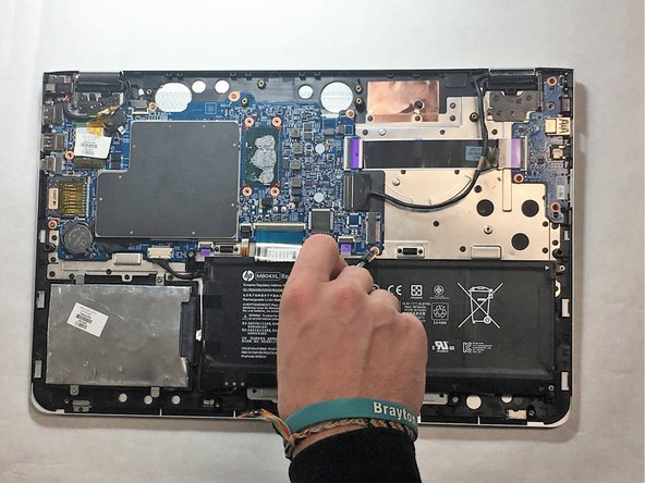
Using your hand, lift and pull the motherboard from inside your computer.
-


Cancelar: No complete esta guía.
Una persona más ha completado esta guía.
Equipo

IUPUI, Team S1-G1, Harley Fall 2018 Miembro de IUPUI, Team S1-G1, Harley Fall 2018
IUPUI-HARLEY-F18S1G1
2 Miembros
2 Guías creadas