Esta versión puede contener ediciones incorrectas. Cambie a la última instantánea verificada.
Qué necesitas
-
Este paso está sin traducir. Ayuda a traducirlo
-
Insert a SIM eject tool, SIM eject bit, or a paperclip into the small hole on the left edge of the phone, near the top.
-
Press to eject the tray.
-
-
-
Calienta un iOpener y aplícalo en el borde superior de la pantalla durante dos minutos.
-
Toma nota de las siguientes regiones antes de comenzar a hacer palanca:
-
Adhesivo delgado revestido contra el panel de la pantalla
-
Adhesivo grueso
-
El panel de visualización OLED, que es muy propenso a sufrir daños
-
El cable de la pantalla, que puede dañarse al hacer palanca
-
-
-
Calienta un iOpener y aplícalo en el borde derecho del teléfono durante dos minutos.
-
Inserta una púa de apertura cerca del borde superior del teléfono, donde ya cortaste el adhesivo.
-
Guía lentamente la púa alrededor de la esquina derecha.
-
Desliza con cuidado la púa por el borde derecho del teléfono para cortar el adhesivo.
-
Repite el paso para el borde izquierdo del teléfono.
-
-
-
-
Retira los siguientes tornillos que aseguran el marco medio a la parte posterior:
-
Siete tornillos negros T5 de 4 mm
-
Dos tornillos T5 plateados de 3 mm
-
-
-
Inserta una púa de apertura separada en el borde derecho del teléfono, cerca de la parte inferior.
-
Empuja lentamente la púa hacia arriba a lo largo de la costura hasta que se suelte el primer clip.
-
Una vez que hayas soltado el clip, deja la púa de apertura en su lugar para evitar que el marco medio se vuelva a sellar.
-
-
Este paso está sin traducir. Ayuda a traducirlo
-
Use the point of a spudger to pry up and disconnect the battery connector.
-
Bend the battery flex cable slightly so that it will not accidentally touch the motherboard.
-
-
Este paso está sin traducir. Ayuda a traducirlo
-
Use the point of a spudger to pry up and disconnect the button strip connector.
-
-
Este paso está sin traducir. Ayuda a traducirlo
-
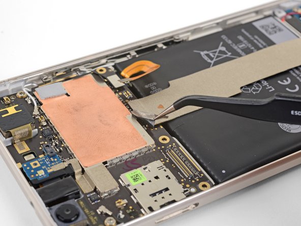
Use tweezers to peel up the tape at the top of the interconnect cable.
-
-
Este paso está sin traducir. Ayuda a traducirlo
-
Use the point of a spudger to pry up and disconnect the interconnect cable from the motherboard.
-
-
Este paso está sin traducir. Ayuda a traducirlo
-
Use the point of a spudger to disconnect the black antenna cable from the motherboard, near the front facing camera module.
-
Route the antenna cable out of its retaining clip.
-
-
Este paso está sin traducir. Ayuda a traducirlo
-
Use the point of a spudger to pry up and disconnect the white antenna cable from the motherboard, near the rear facing camera module.
-
Route the antenna cable out of its retaining clip.
-
-
Este paso está sin traducir. Ayuda a traducirlo
-
Remove the two 3 mm T5 screws securing the motherboard to the frame.
-
-
Este paso está sin traducir. Ayuda a traducirlo
-
Use the point of a spudger to pry up and loosen the front facing camera module from its socket.
-
-
Este paso está sin traducir. Ayuda a traducirlo
-
Insert the point of a spudger into the headphone jack port and pry upwards to loosen the port from its socket.
-
-
Este paso está sin traducir. Ayuda a traducirlo
-
Use the flat end of a spudger to pry the bottom edge of the motherboard up slightly, loosening it from its recess.
-
-
Este paso está sin traducir. Ayuda a traducirlo
-
Locate the fingerprint sensor cable attached to the underside of the motherboard, near the bottom edge.
-
Use the point of a spudger to pry and release the fingerprint sensor cable from its socket.
-
Peel the cable away from the motherboard.
-
-
Este paso está sin traducir. Ayuda a traducirlo
-
Hold the motherboard by the corners and maneuver it out of its recess, being careful not to snag any cables.
-
Bend the fingerprint sensor cable slightly so that it bows upward near the connector.
-
Stand the motherboard up and position it such that the connector rests against the socket.
-
Use your finger to carefully align the connector and press it into the socket. Do not use excessive force! If done correctly, the socket should hold the connector securely.
-
-
Este paso está sin traducir. Ayuda a traducirlo
-
Position your thumb over the fingerprint sensor and push firmly until the sensor pops out of its indention.
-
-
Este paso está sin traducir. Ayuda a traducirlo
-
Remove the fingerprint sensor.
-
Align the fingerprint sensor's connector to the motherboard socket, which is located on the underside near the battery edge.
-
Use your finger to press the connector into the socket. Do not use excessive force! The connector should click into position if done correctly.
-
-
Este paso está sin traducir. Ayuda a traducirlo
-
Move the motherboard into position near its recess.
-
Use your finger to press the fingerprint sensor down into its indentation.
-
Be sure that the sensor is properly aligned in the indentation.
-
Continue with the reassembly.
-


Cancelar: No complete esta guía.
6 personas más completaron esta guía.

