Esta versión puede contener ediciones incorrectas. Cambie a la última instantánea verificada.
Qué necesitas
-
Este paso está sin traducir. Ayuda a traducirlo
-
Using a metal spudger, push down between the edge seals on the base and pry off the base.
-
-
Este paso está sin traducir. Ayuda a traducirlo
-
Use the T-10 bit from the iFixit tool kit to unscrew the four 1.4 inch corner screws on top of the first layer.
-
-
Este paso está sin traducir. Ayuda a traducirlo
-
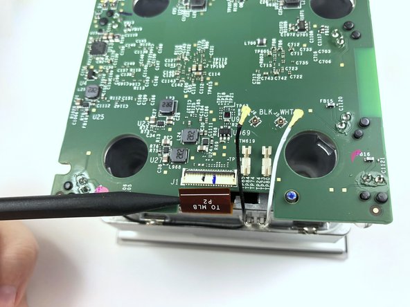
Lift the black latch by gently prying up with the flat end of the Spudger.
-
Detach the copper tap by pulling it out.
-
-
-
Este paso está sin traducir. Ayuda a traducirlo
-
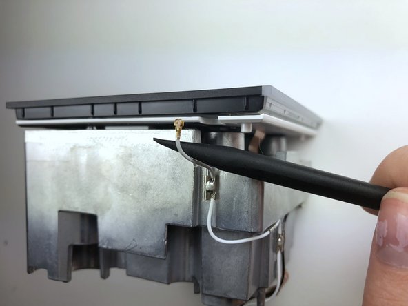
Use the pointed end of the Spudger to carefully detach the black and white wires from the motherboard.
-
-
Este paso está sin traducir. Ayuda a traducirlo
-
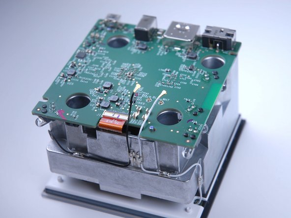
Detach the wires from the opposite end of the frame using the flat end of the Spudger.
-
-
Este paso está sin traducir. Ayuda a traducirlo
-
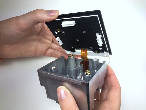
Lift the black latch to detach the copper tab by gently prying with the Angled Tweezers.
-
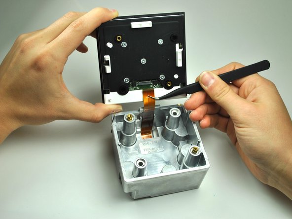
Use the Angled Tweezers to carefully pull out the copper tab.
-
-
Este paso está sin traducir. Ayuda a traducirlo
-
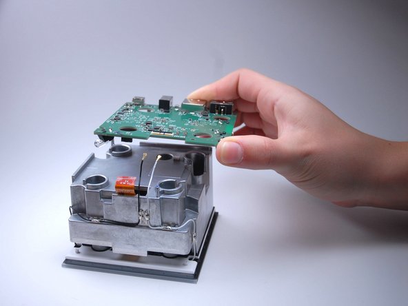
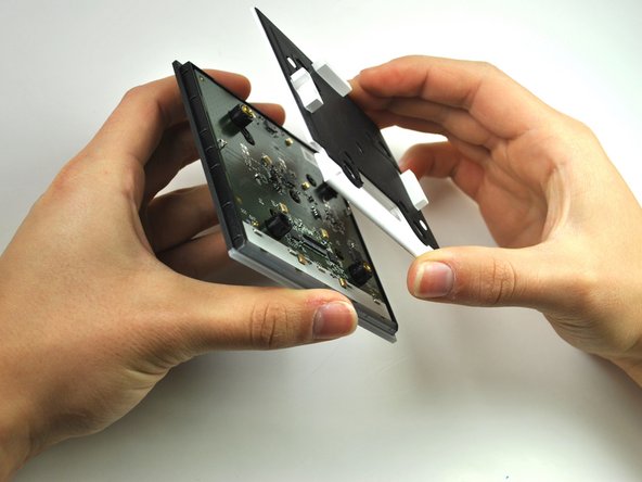
Lift and remove white the frame to reveal the circuit board.
-
-
Este paso está sin traducir. Ayuda a traducirlo
-
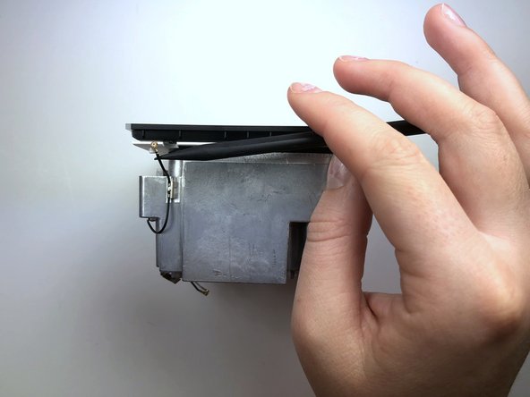
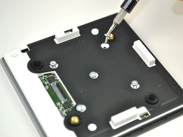
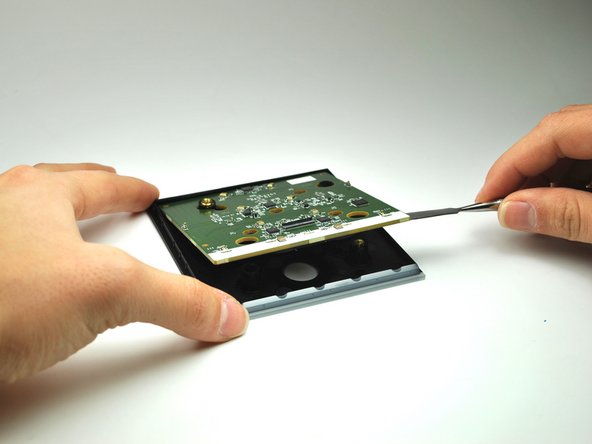
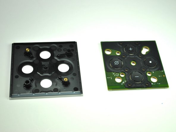
Using a the Metal Spudger, pry up the circuit board to reveal a rubber button panel.
-


Equipo

Linn Benton Community College, Team S1-G1, Johnson Fall 2018 Miembro de Linn Benton Community College, Team S1-G1, Johnson Fall 2018
LBCC-JOHNSON-F18S1G1
4 Miembros
5 Guías creadas
Un comentario
A suggestion for step 8: the antenna wires are not soldered to the aluminum heatsink; they are soldered to small clips that are easily popped off from the heatsink. I found it much easier to pop off all the clips and free the antenna wires from the heatsink than try to remove the antenna connectors from the top circuit board while it is still attached to the frame. After removing the top circuit board from the frame, it’s then much easier to remove the antenna connectors.