@miguelange57370 how/why did you update the firmware? Did the backlight work before? Do both screens have known working backlights for sure?
Your logic board should be a 820-3126-A. Try this:
inspect and reseat the following cable connections:
- Output cable between lower end of LED backlight board and lower end of LCD panel.
- Vertical sync cable between upper end of LED backlight board and LCD panel.
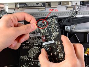
- DC power cable between upper right of LED backlight board and power supply.
- Replace any damaged cable.
- Reinstall LCD panel
Inspect and reseat DisplayPort cable between LCD panel and logic board.
Check the power to your inverter (4 pin or 6 pin connector?) to make sure that your inverter gets power. The left and right outside connectors are the power connectors.
There is a possibility that your back;light enable circuitry may have issues. Here is the schematic for that. See if all of those parts are functioning. Check for the 3.3V on your inverter as well. It is one of the inner contacts on the inverter connector
Translation
@miguelange57370 ¿cómo/por qué actualizaste el firmware? Funcionaba antes la retroiluminación? ¿Se sabe con certeza si ambas pantallas tienen retroiluminación que funcione?
Tu placa lógica debería ser una 820-3126-A. Intente esto:
inspeccione y vuelva a colocar las siguientes conexiones de cable:
- Cable de salida entre el extremo inferior de la placa de retroiluminación LED y el extremo inferior del panel LCD.
- Cable de sincronización vertical entre el extremo superior de la placa de retroiluminación LED y el panel LCD.
- Cable de alimentación de CC entre la parte superior derecha de la placa de retroiluminación LED y la fuente de alimentación.
- Sustituya cualquier cable dañado.
- Vuelva a instalar el panel LCD
- Inspeccione y vuelva a colocar el cable DisplayPort entre el panel LCD y la placa lógica.
Compruebe la alimentación del inversor (¿conector de 4 o 6 patillas?) para asegurarse de que el inversor recibe alimentación. Los conectores exteriores izquierdo y derecho son los conectores de alimentación.
Existe la posibilidad de que el circuito de habilitación de la luz trasera tenga problemas. Este es el esquema. Mira si todas esas partes funcionan. Compruebe los 3.3V en su inversor también. Es uno de los contactos internos en el conector del inversor
@miguelange57370 Here is the connector for your inverter.
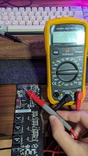
Let us know what voltages you get. those are DC voltages. If you do not get the BLO Backlight on Voltage, your inverter does not get the signal to turn the backlights on. In that case you would need to check the circuitry on the logicboard.
Translation
@miguelange57370 Aquí tienes el conector para tu inversor.
[imagen|3158319]
Haznos saber que voltajes obtienes, esos son voltajes DC. Si no obtienes el BLO Backlight on Voltage, tu inversor no recibe la señal para encender las luces de fondo. En ese caso tendrías que comprobar los circuitos de la placa lógica.
@miguelange57370 in your case it will not be 12V but 3V
[imagen|3161792]
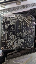
@miguelange57370 LED driver board DC power connector
PSU connector pinout
@miguelange57370 try this now. Pin 1 is ground :-)
@miguelange57370 trying to figure out which contact on the connector those two wires are. Can you see them going into the connector?
@miguelange57370 one more close up. This time of the are i outlined.
(Pin 2 is GND pin 4 is BL enable)
@miguelange57370 here is the schematic for J601
@miguelange57370 okay so here is what the back connector looks like.
@miguelange57370 continuity on J601
@miguelange57370
CN 1 from power board to LED driver
@miguelange57370 should look like this
@miguelange57370 Connector A and connector B
@miguelange57370 backlight connection
@miguelange57370 disconnect the LCD backlight connector for the display
@miguelange57370 J602 is the logicboard to backlight connector.
@miguelange57370 DP connector circuitry


1 comentario
@miguelange57370 I am off tomorrow so we can start working on this earlier. It's almost morning where you are
- de oldturkey03