Saltar al contenido principal

Soldering Novice SNAFU...Am I screwed?

Hello friends. I have been battling a Samsung TV with startup issues. I replaced capacitors successfully about a year ago. Then started in last few months having startup issues again. Through some suggestions on here and recon online and checking some voltages from power supply (which are good), I feel that my main board is the problem.

I found a youtube and some DIY's which explained that the main board creating startup issues is related to two specific parts (surface mount chips) on the back of the board...

I own a soldering iron, and I am a NOVICE at soldering. But I decided to attempt to remove the chips BEFORE buying replacements, just in case... Well after about 2 hours of work, (they only took 2 minutes in the video!) I think i have killed my board. I need a damage assessment. Take a peek...

Am I screwed?

Block Image

Block Image

http://s277.photobucket.com/user/Paintuf...http://s277.photobucket.com/user/Paintuf...

Contestado! Ver respuesta Yo también tengo este problema

Es esta una buena pregunta?

Puntuación 0
Agregar un comentario

2 Respuestas

Solución Elegida

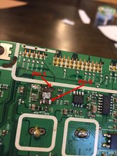
It looks like you've lifted the tracks on all but a couple of the pads. All is not lost, but you will need:

  • A soldering iron with a 1mm or finer bit
  • Some fine solder - 22SWG or finer
  • Solder braid
  • Flux pen
  • Some thin wire, e.g. a few single strands from some stranded wire.

First of all, clean up the pads. Put some flux from the flux pen on the braid, then press the braid down onto the soldered pads with the soldering iron. (A standard bit is better for this.) The braid will soak up all excess solder.

You only have 2 good pads (3 at a pinch) to solder the replacement chip to. (You did note which way round the original was, didn't you?)

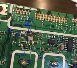
Position the new chip on the pads, and get someone to gently hold it down with a small screwdriver. Or you may be able to hold it down with a sliver of double-sided tape. Apply flux to the pins you're going to solder. Apply the iron (fine tip) to one of the pins and after a second or two, feed in a little solder. Not too much or it'll bridge to the next pin. (You can put that right with the braid.) Hold the iron like a pencil, close to the element and rest your wrist on the bench, so as to get the finest possible control. If your youth is receding you may find a cheap pair of readyspecs of 1 - 2 dioptres will allow you to work much closer.

Repeat with the other surviving pad, and if possible, the 3rd. You may just be able to solder one of the pins on the other side to the remnants of the track.

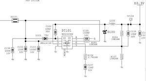
For the other pins, you'll need to connect them with the fine wire. The trashed track from the remaining pin on the bottom clearly goes to R105. Solder one end of a piece of wire to the pin and the other end to the solder end of R105, or else gently scrape the green solder resist off the track and solder direct to that. (Always use flux.)

I can't quite see from the photo where the tracks from the pins on the other side were meant to go but hopefully you can with a good light and a magnifying glass.

Once you've got all the pins connected, check for solder bridges with a magnifying glass and very gently pull each of the wires to make sure its secure. Now test to see if it works. If it does, the new chip will need holding in place with something like hot melt glue.

Good luck!

Fue útil esta respuesta?

Puntuación 2

2 comentarios:

First off, wow and thank you!

Second, logistical question. Assuming I can use @oldturkey03 's chart and your input and my magnifying glass to figure out where each wire goes. Some of them are going to be pretty close together, is there any trick to keeping a bunch of teeny tiny exposed copper wires from touching each other? (like the big loop part between connections).

I am discussing with the wife for the OK to blow $50 more on the TV for something I MIGHT be able to pull off, lol. I will keep you updated! I am looking forward to the challenge, I have most of the stuff you mentioned already, but I have ZERO experience with FLUX and braid...well see where that takes me.

Last question, looking at @oldturkey03 's chart, at pin 1... It connects to D103 and C104...

UPDATE: I found C104 & D103...they're on the other side of the board!??

Thanks again, your input is invaluable for new folks like myself!

- de

@paintufast "they're on the other side of the board!??" quite possible since your board is a multilayer board. You can run wires all across the boards etc. However, at this point I'd follow what @pleriche says about cleaning the board. Wash it down with some isopropyl alcohol (nothing less that 90% available at hardware stores, pharmacies etc. and a soft brush). Then use the flux and braid to clean the pads. Post some good pictures once it is cleaned there may be enough of the traces left to solder to. You only need one strand of wire to go from point to point. I commonly use a single strand from some LVDS cable or from a speaker cable. Old transformer wires work as well since they are insulated. There is not a whole lot of amperage/voltage on those wires to worry about the thickness to much. What you do want to do so is to practice. Get an old board from anything and practice the soldering/desoldering. The trick is the right heat and you will need flux. If to cold you may tear off the solder pads when you remove the component, to much heat and you melt of the solder pads. Practice will be the key for this repair. Some videos on youtube should give you a good idea

https://www.youtube.com/watch?v=cTnVg6Pm... and https://www.youtube.com/watch?v=2s9afn7i...

http://www.circuitrework.com/guides/6-1.... for ideas about jumper wires.

You can get some special insulation paint for the jumper wires or use some good old fashioned acrylic nail polish:-)

- de

Agregar un comentario
Respuesta Más Útil

@paintufast not quite yet:-) Follow the excellent advice given by @pleriche This is only an augmentation to his excellent answer. You can connect the IC to the nearest components as is described in that answer. These images should help you with that.

Block Image

Block Image

Update (11/07/2017)

Here is a bit of an update. Hope it is not to confusing. I used color line so you can see where to connect the thin wires to. Your view does not show components like C104,D103 etc. A good straight show onto the board may reveal where they are.

Block Image

Fue útil esta respuesta?

Puntuación 3

1 comentario:

Oh boy, I need to learn how to read that chart I see. This is going to be very helpful. I am inspired and think I will order these little tidbits I need from the above post, and the chips and give her a shot. Can't hurt! Thanks for the advice! Learning everyday!

- de

Agregar un comentario

Añadir tu respuesta

Pete Richison estará eternamente agradecido.
Ver Estadísticas:

Ultimas 24 horas: 0

Ultimos 7 días: 0

Ultimos 30 días: 1

Todo El Tiempo: 183