Esta versión puede contener ediciones incorrectas. Cambie a la última instantánea verificada.
Qué necesitas
-
-
Afloja el único tronillo Phillips en el contro de la puerta de acceso.
-
Quita la puerta de acceso de tu iMac.
-
-
-
Pega dos ventosas en las esquinas opuestas del panel de vidrio.
-
-
-
-
Retira los siguientes 12 tornillos que sujetan el bisel frontal a la carcasa trasera:
-
Ocho Torx T8 de 13 mm.
-
Cuatro Torx T8 de 25 mm.
-
-
-
Coloca las manos en las esquinas superiores del bisel (hacia un lado) y levanta el bisel de 2 a 3 cm del cuerpo trabajando desde la parte superior. Después de esto, también puedes desenganchar la parte inferior del bisel (los módulos de memoria evitarán que la parte inferior del bisel se separe primero).
-
Al volver a armar, comienza con la parte inferior del bisel.
-
Para separar completamente el bisel: desconecta el conector del cable del micrófono, quitando la cinta según sea necesario.
-
Para mantenerlo conectado, deja el cable del micrófono conectado a la placa lógica y coloca el bisel "sobre" el chasis, con el cable del micrófono formando una bisagra.
-
-
-
asegúrate de colocar el cable del micrófono y el conector en el espacio vacío junto a la placa de la cámara.
-
Guía con cuidado el conector del micrófono y los cables a través de la ranura de ±1 pulgada de largo a la derecha de la cámara iSight. Una vez que el bisel esté correctamente ensamblado, empuja suavemente el conector del micrófono y el cable dentro del bisel a través de esa ranura.
-
-
Este paso está sin traducir. Ayuda a traducirlo
-
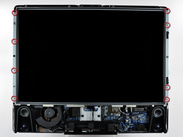
After removing the front bezel, you need to remove the 8ea 12mm T8 screws around the perimeter of the LCD
-
-
Este paso está sin traducir. Ayuda a traducirlo
-
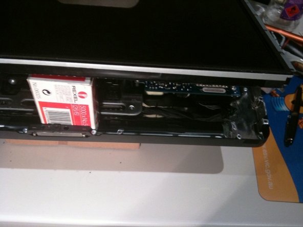
Use the chart provided as a reference and test the various voltages with your meter being sure to restrict the probes to the 10 solder joints on the PSU connector shown within the BLUE rectangle. Shorting any part of the PCB will almost certainly cause damage to the imac
-
All voltage measurements are taken with PIN 1 as reference (Marked with the YELLOW square). Pin 1 is marked on the board by a dot and is the right hand pin when viewed as shown in photos
-
Reassemble your iMac in reverse order. When lowering the LCD ensure you don't crimp or crush the LCD back-light cables
-


Cancelar: No complete esta guía.
20 personas más completaron esta guía.

Equipo

10 comentarios
Something I don't get…
I'm investigating on my mid2007 iMac power problems and I don't get the same results of voltage as in this article. In my case, number 9 is at around 12V and number 8 is at 0V.
Is my PSU really faulty or there might be some other PSU models?
I've got the same results as you. Wondering if we have the wrong ps model, despite being what iFixit recommends and sells. Very odd.
i have the same issue. Do we have the wrong power supply or the wrong voltage chart?
Have also the same, maybe the table here is wrong. What kind of problems does your mac have?