Esta versión puede contener ediciones incorrectas. Cambiar a la última instantánea verificada.
Qué necesitas
-
-
Use una moneda para girar el tornillo de bloqueo de la batería 90 grados en el sentido de las agujas del reloj.
-
-
Este paso está sin traducir. Ayuda a traducirlo
-
Pull the keyboard release tabs toward you and lift up on the keyboard until it pops free.
-
Flip the keyboard over, away from the screen, and rest it face-down on the trackpad area.
-
-
Este paso está sin traducir. Ayuda a traducirlo
-
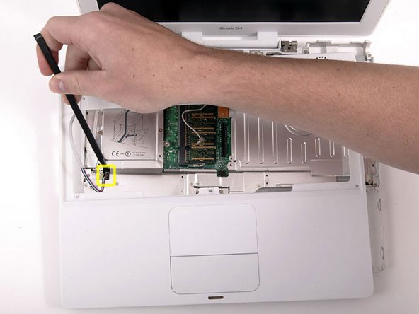
Push the wire clasp away from the AirPort card and toward the display, then rotate up to free it from the RAM shield.
-
-
Este paso está sin traducir. Ayuda a traducirlo
-
Grasp the clear plastic tab on the AirPort card and pull toward the display.
-
-
Este paso está sin traducir. Ayuda a traducirlo
-
Hold the AirPort card in one hand and use your other hand to remove the antenna cable.
-
-
Este paso está sin traducir. Ayuda a traducirlo
-
Remove the four silver Phillips screws that secure the RAM shield.
-
-
Este paso está sin traducir. Ayuda a traducirlo
-
Grasp the metal bracket on top of the RAM shield and pull upward to remove the shield.
-
-
Este paso está sin traducir. Ayuda a traducirlo
-
Pull the keyboard cable up from the logic board, holding the cable as close to the connector as possible.
-
-
-
Hay una ranura en la pared del compartimiento de la batería que bloquea la carcasa inferior en su lugar. Use un destornillador pequeño de cabeza plana para levantar el borde inferior de la ranura y tire hacia arriba de la carcasa inferior para liberar la ranura de las pestañas que la sujetan.
-
-
-
Ejecute un spudger a lo largo de la costura entre la minúscula y la mayúscula en la parte frontal de la computadora para liberar las pestañas que bloquean la carcasa inferior. Tire hacia arriba de la carcasa inferior y continúe utilizando el spudger según sea necesario hasta que oiga tres clics distintos.
-
-
Este paso está sin traducir. Ayuda a traducirlo
-
Continue to run the spudger around the front, right corner. There are two tabs on the port side of the computer, one near the front corner and one near the sound-out port.
-
-
Este paso está sin traducir. Ayuda a traducirlo
-
There are three tabs over the optical drive that must be released before the lower case can come off. Slide the spudger into the lower case above the optical drive and run it toward the back of the computer until you hear three distinct clicks.
-
-
Este paso está sin traducir. Ayuda a traducirlo
-
Once the front and sides of the lower case are free, turn the computer so that the back is facing you and pull the lower case up and away from you until the back tabs pop free.
-
-
-
Este paso está sin traducir. Ayuda a traducirlo
-
Remove the small greasy springs with white plastic caps from either side of the battery contacts.
-
-
Este paso está sin traducir. Ayuda a traducirlo
-
Remove the two Phillips screws securing the DC-In board.
-
-
Este paso está sin traducir. Ayuda a traducirlo
-
Deroute the cable from around the optical drive, removing tape as necessary, and angle the DC-In board out of its compartment.
-
-
Este paso está sin traducir. Ayuda a traducirlo
-
Remove the two Phillips screws from the battery compartment.
-
-
Este paso está sin traducir. Ayuda a traducirlo
-
Turn over the computer and open it.
-
Pry up the magnet covering a Phillips screw near the middle of the computer.
-
-
Este paso está sin traducir. Ayuda a traducirlo
-
Remove the following 7 screws from the edges of the keyboard area.
-
Three 2 mm Phillips along the right edge.
-
One 4.5 mm Phillips underneath where the magnet was.
-
One 6 mm Phillips with a small head in the lower left corner.
-
Two 6 mm Phillips with large heads, one in the upper left corner and one in the middle
-
-
Este paso está sin traducir. Ayuda a traducirlo
-
Lift the upper case from the right side and use a spudger or your finger to disconnect the trackpad connector hidden beneath the white plastic tab. Due to model variatons your trackpad connector may be different from the one pictured.
-
-
Este paso está sin traducir. Ayuda a traducirlo
-
Carefully lift the upper case about half of an inch and move it so that you can access the power and speaker cables.
-
-
Este paso está sin traducir. Ayuda a traducirlo
-
Lift the upper case enough to disconnect the blue and white power cable from the logic board. Using your fingernails or a dental pick, carefully pry the connector from its socket. Make sure you're pulling only on the connector and not on the socket.
-
-
Este paso está sin traducir. Ayuda a traducirlo
-
Lift the upper case off completely and disconnect the multicolored speaker cable from the logic board. As before, make sure you're pulling only on the connector and not on the socket.
-
-
Este paso está sin traducir. Ayuda a traducirlo
-
Remove the following 15 screws:
-
Fourteen 3 mm Phillips.
-
One 5.5 mm Phillips in the upper left corner.
-
-
Este paso está sin traducir. Ayuda a traducirlo
-
Lift the top shield up from the right side, minding the upper left corner, which may catch on the metal framework.
-
-
Este paso está sin traducir. Ayuda a traducirlo
-
Remove the two Phillips screws at the corners of the modem.
-
-
Este paso está sin traducir. Ayuda a traducirlo
-
Disconnect the RJ-11 cable from the top of the modem.
-
-
Este paso está sin traducir. Ayuda a traducirlo
-
Lift the metal restraining bracket from the hard drive and place it aside.
-
-
Este paso está sin traducir. Ayuda a traducirlo
-
Remove the two Phillips screws securing the hard drive to the metal framework.
-
-
Este paso está sin traducir. Ayuda a traducirlo
-
Lift the hard drive up and remove the metal bracket, then carefully lower the hard drive back into its compartment.
-
-
Este paso está sin traducir. Ayuda a traducirlo
-
Remove the two Phillips screws from the white plastic fingers of the hinge grill.
-
-
Este paso está sin traducir. Ayuda a traducirlo
-
Remove the following 5 screws and 3 nuts from the heat sink:
-
One 3.5 mm Phillips from the lower left corner of the heat sink.
-
Three 6 mm Phillips from around the fan.
-
One 7.5 mm Phillips at the top right corner of the heat sink.
-
One 4 mm nut from the side of the heat sink.
-
Two 4 mm screw nuts with attached springs from either side of the heat sink.
-
-
Este paso está sin traducir. Ayuda a traducirlo
-
Use a spudger to pry the heat sink up on the left side, near the hard drive.
-
-
Este paso está sin traducir. Ayuda a traducirlo
-
Grasp the heat sink in one hand and lift up the hinge grill in the other hand so that you can remove the heat sink from the computer.
-
-
Este paso está sin traducir. Ayuda a traducirlo
-
Remove the two Phillips screws securing the white plastic fingers of the I/O bezel to the metal framework.
-
-
Este paso está sin traducir. Ayuda a traducirlo
-
Lift up the left side of the computer and slide the I/O bezel away.
-
-
Este paso está sin traducir. Ayuda a traducirlo
-
Remove the single Phillips screw securing the EMI finger to the metal framework.
-
Lift the silver EMI finger off of the metal framework.
-
-
Este paso está sin traducir. Ayuda a traducirlo
-
Wedge a spudger between the RJ-11 board and the metal framework and slide the RJ-11 board down and off of the logic board.
-
-
Este paso está sin traducir. Ayuda a traducirlo
-
Disconnect the microphone cable at the front of the computer, between the left side of the hard drive and the metal framework.
-
-
Este paso está sin traducir. Ayuda a traducirlo
-
Use the black plastic handle to disconnect the display data cable from the logic board.
-
-
Este paso está sin traducir. Ayuda a traducirlo
-
There are two different styles of optical drive ribbon. If the cable extending from the optical drive is white, skip this step. If the cable is orange, then complete this step and skip the next two steps.
-
Disconnect the orange optical drive ribbon from the logic board.
-
-
Este paso está sin traducir. Ayuda a traducirlo
-
This is a diagram of the ribbon clamp connector you will disconnect in the next step.
-
1) With your fingernails, grasp the locking bar on either side and pull up a small amount (about 1/16" or 2 mm).
-
2) After disengaging the locking bar, slide the cable out of the connector.
-
-
Este paso está sin traducir. Ayuda a traducirlo
-
Release the optical drive ribbon clamp as described above. Slide the optical drive ribbon out of its connector.
-
-
Este paso está sin traducir. Ayuda a traducirlo
-
Hold the hard drive in place with one hand while tilting the computer up.
-
Disconnect the orange ribbon cable from the logic board.
-
-
Este paso está sin traducir. Ayuda a traducirlo
-
Lift the hard drive up, carefully guiding the cable through the slot in the lower case.
-
-
Este paso está sin traducir. Ayuda a traducirlo
-
Close the display and flip the computer over.
-
Remove the following 10 screws:
-
Seven 3 mm Phillips.
-
One 3 mm Phillips with a thicker shaft at the bottom right corner of the logic board, next to the fan.
-
Two 7.5 mm Phillips on either side of the battery connector.
-
-
Este paso está sin traducir. Ayuda a traducirlo
-
Disconnect the inverter, fan, and sleep light cables from the logic board.
-


Cancelar: No complete esta guía.
17 personas más completaron esta guía.
Documentos Adjuntos

Un comentario
Just finished putting back together my iBook G4 12inch 1.92. After attempting to repair the infamous soldering issue of these machines, I put it back together and… it works! Thank you for your detailed instructions. If I had one suggestion, please list the screw sizes at all the steps for those putting things back together afterwards. Thank you again!