Saltar al contenido principal

Esta versión puede contener ediciones incorrectas. Cambie a la última instantánea verificada.

Qué necesitas

  1. Este paso está sin traducir. Ayuda a traducirlo

    : paso 1, imagen 1 de 1
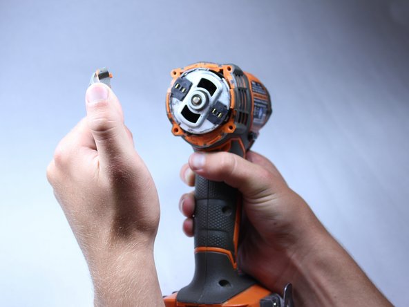
    • Use the flat side of a metal spudger to peel the black rubber cover off of the casing.

    • Use some force; the rubber cover is securely attached to the housing.

    • Rotate the casing until it fits onto the housing with no gaps between it and the clear cover.

    • Orientation is important when putting the rubber cover on the casing.

  2. Este paso está sin traducir. Ayuda a traducirlo

    : paso 2, imagen 1 de 2 : paso 2, imagen 2 de 2
    • Remove the plastic cover with your hands.

    • There is no need to force off the plastic cover. The plastic cover should be much easier to remove than the rubber cover.

  3. Este paso está sin traducir. Ayuda a traducirlo

    : paso 3, imagen 1 de 3 : paso 3, imagen 2 de 3 : paso 3, imagen 3 de 3
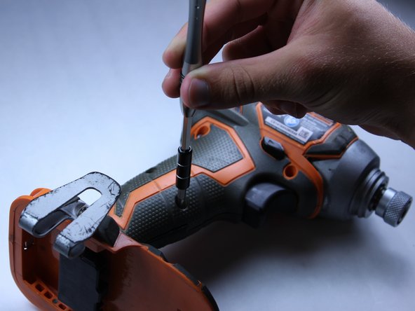
    • Unscrew the four 16 mm long screws from the back panel with a T10 Torx Screwdriver.

    • Use a firm grip to peel off the back panel. It is sealed tight and requires a good amount of force to remove.

  4. Este paso está sin traducir. Ayuda a traducirlo

    : paso 4, imagen 1 de 2 : paso 4, imagen 2 de 2
    • Unscrew the eight 15 mm T10 Torx screws from the housing

    • The screw hole located nearest the battery port is deep and small. Most screwdrivers with replaceable bits will not fit into the hole. Instead, use a conventional screwdriver that fits.

  5. Este paso está sin traducir. Ayuda a traducirlo

    : paso 5, imagen 1 de 1
    • Place the driver flat on a table before completely separating the two halves of the housing so components of the drill don't fall out during opening.

    • Pry apart the two halves of the housing at the back side of the driver using the metal spudger.

    • The housing is easier to remove if you pry from multiple sides.

  6. Este paso está sin traducir. Ayuda a traducirlo

    : paso 6, imagen 1 de 2 : paso 6, imagen 2 de 2
    • Do not remove the direction switch.

    • Pull out all electrical components from housing by hand.

    • Lift out the motor.

    • Follow the wires.

    • The components should come out of their respective slots with ease and require little force to lift out.

    • The circuit board located nearest the battery pack and the LED light will be hard to pull out.

    • Remember to precisely place all components in their correct slots with their correct orientations when reassembling.

  7. Este paso está sin traducir. Ayuda a traducirlo

    : paso 7, imagen 1 de 1
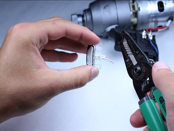
    • Identify the LED light. The LED light is the component with clear casing and has two wires attached, located toward the bottom of the driver.

  8. Este paso está sin traducir. Ayuda a traducirlo

    : paso 8, imagen 1 de 3 : paso 8, imagen 2 de 3 : paso 8, imagen 3 de 3
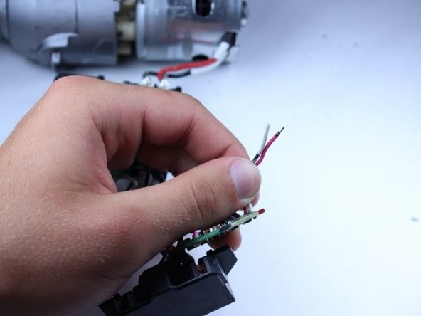
    • Cut the pink and white wires attached to the LED at a point that is a little more than 1/4 inch from the LED.

  9. Este paso está sin traducir. Ayuda a traducirlo

    : paso 9, imagen 1 de 1
    • Strip the wires back about 1/4 inch on the LED.

  10. Este paso está sin traducir. Ayuda a traducirlo

    : paso 10, imagen 1 de 2 : paso 10, imagen 2 de 2
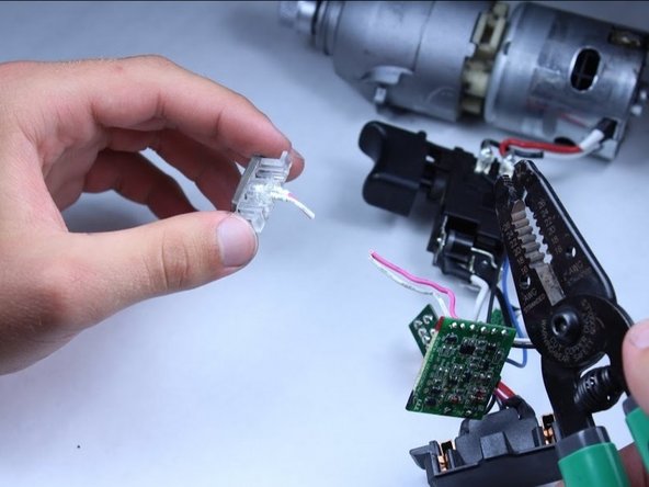
    • Strip the wires that were connected to the LED on the circuit board to approximately 1/4 inch.

  11. Este paso está sin traducir. Ayuda a traducirlo

    : paso 11, imagen 1 de 1
    • Solder the new LED striped wires to the wire attached to the circuit board.

    • Wrap the soldered connection with electrical tape, to ensure that the circuit isn't shorted.

Linea de Meta

Sean Liston

Miembro Desde 04/28/15

311 Reputación

2 Guías creadas

Equipo

Cal Poly, Team 15-5, Amido Spring 2015 Miembro de Cal Poly, Team 15-5, Amido Spring 2015

CPSU-AMIDO-S15S15G5

4 Miembros

12 Guías creadas

0 comentarios

Agregar Comentario

Ver Estadísticas:

Ultimas 24 horas: 3

Ultimos 7 días: 12

Ultimos 30 días: 17

Todo El Tiempo: 1,130