Esta versión puede contener ediciones incorrectas. Cambie a la última instantánea verificada.
Qué necesitas
-
Este paso está sin traducir. Ayuda a traducirlo
-
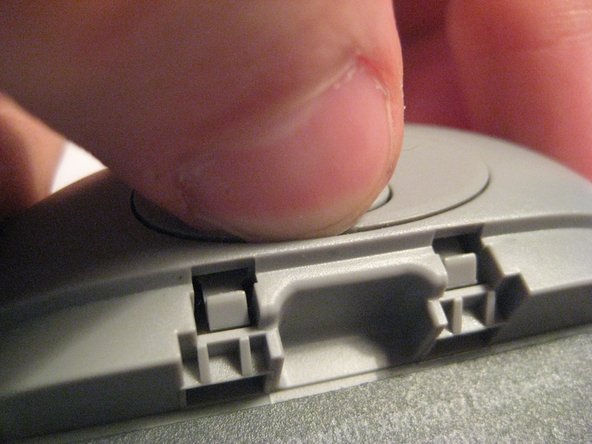
Locate the large button on the top of the device.
-
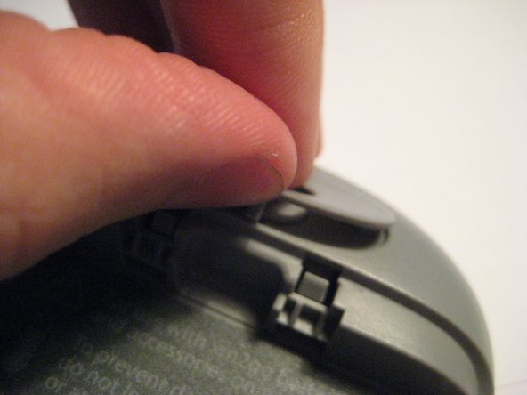
Push down on the button and slide the cover away from the button.
-
-
Este paso está sin traducir. Ayuda a traducirlo
-
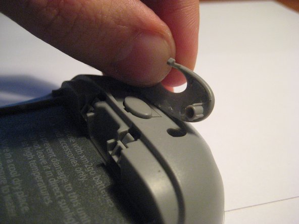
Grab the red pull tab and pull down to unlock the latch.
-
Pull the battery out.
-
-
Este paso está sin traducir. Ayuda a traducirlo
-
Remove the four screws from the bottom of the device using a T6 Torx screwdriver.
-
-
Este paso está sin traducir. Ayuda a traducirlo
-
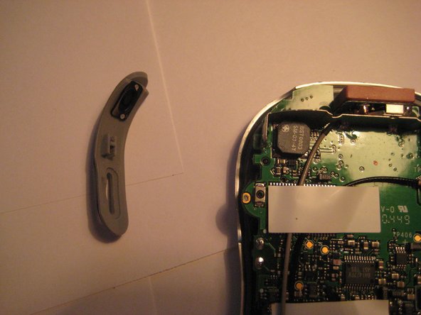
Remove the button cover on the back of the device by prying it up with a spudger or your thumb nail.
-
-
-
Este paso está sin traducir. Ayuda a traducirlo
-
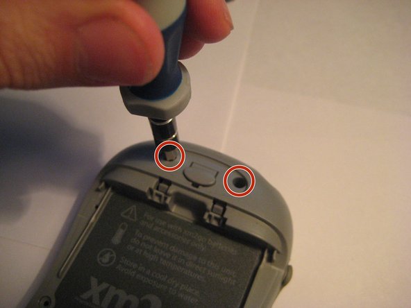
Remove the two screws under the button using the T6 Torx screwdriver.
-
-
Este paso está sin traducir. Ayuda a traducirlo
-
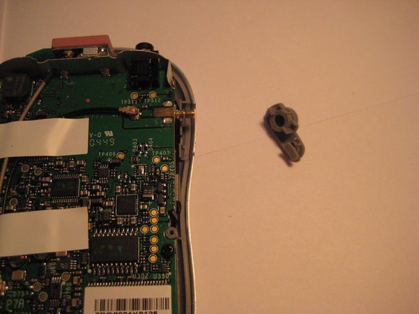
Remove the plastic antenna extension connector on the right side of the device.
-
-
Este paso está sin traducir. Ayuda a traducirlo
-
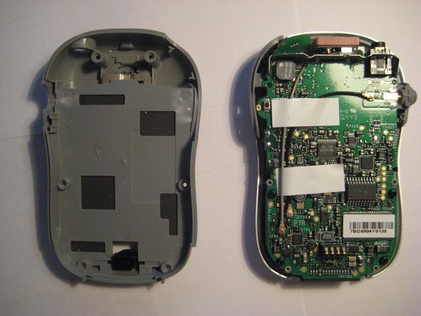
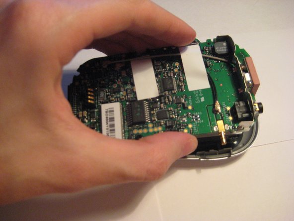
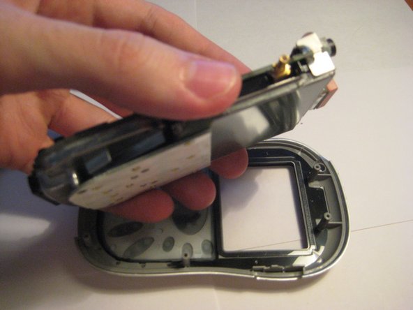
Pull up on the motherboard to remove it from the device.
-
-
Este paso está sin traducir. Ayuda a traducirlo
-
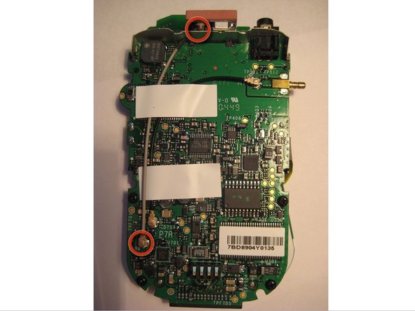
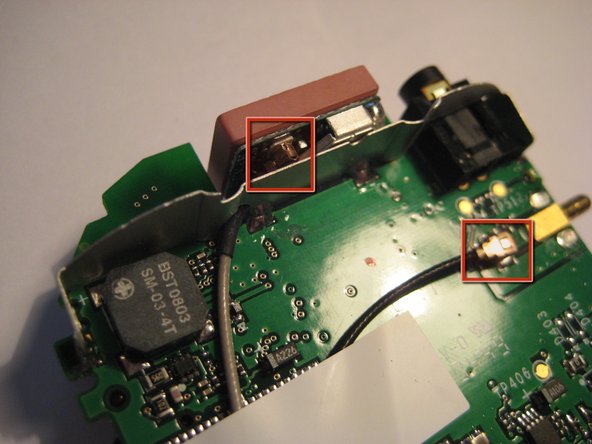
In the first picture, a connection may be seen with the black cable connecting the external antenna connector to the internal logic board (PCB) via U.FL connectors. The connectors on the ends of the cable are circled in red.
-
In the second picture, a connection may be seen with the with the gray cable connecting the external antenna connector to the internal logic board (PCB) via U.FL connectors. The connectors on the ends of the cable are circled in red.
-
-
Este paso está sin traducir. Ayuda a traducirlo
-
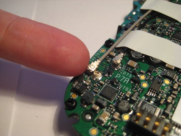
These antenna cables may need to be replaced should the connection drop from the XM Satellite service.
-
To remove, catch the side of the connector with a fingernail moving upward until the connectors pops up from the board.
-
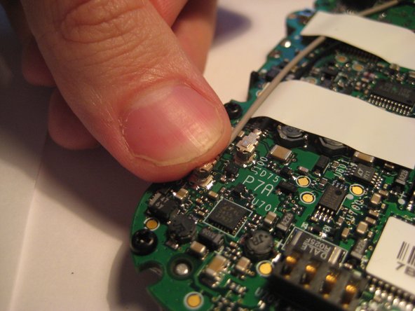
After the U.FL connector is loose, center the new connector cable over the mating U.FL connector and press down firmly.
-
-
Este paso está sin traducir. Ayuda a traducirlo
-
The U.FL antenna connectors should be secure and immobile as shown in the pictures.
-
Try moving them back and forth on the board to assure they are secure.
-
The U.FL antenna connectors are shown to be secure in the pictures highlighted with red boxes.
-


Equipo

Clemson, Team 1-2, Benson Spring 2012 Miembro de Clemson, Team 1-2, Benson Spring 2012
CLEM-BENSON-S12S1G2
3 Miembros
9 Guías creadas