Saltar al contenido principal

Esta versión puede contener ediciones incorrectas. Cambie a la última instantánea verificada.

Qué necesitas

  1. , Tapa inferior: paso 1, imagen 1 de 1
    • Retire los ocho tornillos Phillips de 4 mm que sujetan la carcasa inferior al MacBook.

  2. : paso 2, imagen 1 de 3 : paso 2, imagen 2 de 3 : paso 2, imagen 3 de 3
    • La carcasa inferior está construida de aluminio recubierto de goma. No doble excesivamente el aluminio durante la extracción, ya que cualquier deformación permanente causará problemas de tolerancia después del reensamblaje.

    • Levante ligeramente la tapa inferior cerca de la abertura de ventilación.

    • Continúa pasando los dedos entre la parte superior e inferior hasta que salgan los clips de retención.

    • La ubicación de estos tres clips se muestra en la tercera imagen.

  3. , Batería: paso 3, imagen 1 de 1
    • Por precaución, aconsejamos que desconectes el conector de la batería de la placa lógica para evitar ninguna descarga eléctrica. Este paso es opcional y no es requerido.

    • Usar la punta plana de una spudger para levantar el conector de la batería de su enchufe en la placa lógica.

    • Puede ser mas fácil usar tus uñas para levantar el conector en ambos lados

  4. , Rejilla Trasera: paso 4, imagen 1 de 1
    • Remueve los siguientes tornillos del lado del disco óptico de la rejilla trasera:

    • Dos Torx T8 de 10mm

    • Dos Phillips de 5.2mm

  5. : paso 5, imagen 1 de 1
    • Remueve los siguientes tornillos del lado de los puertos de la rejilla trasera:

    • Dos Torx T8 de 10mm

    • Dos Phillips de 5.2mm

  6. : paso 6, imagen 1 de 1
    • Cuidadosamente levanta la rejilla trasera afuera de la carcasa.

  7. , Placa Logica: paso 7, imagen 1 de 1
    • Usa el lado plano de un spudger para levantar el cable plano del Airport/Bluetooth de la placa lógica.

  8. : paso 8, imagen 1 de 3 : paso 8, imagen 2 de 3 : paso 8, imagen 3 de 3
    • Usa un spudger para levantar el conector del ventilador hacia arriba y fuera de su zocalo en la placa lógica.

    • Es útil torcer el spudger axialmente de debajo del loa cables del ventilador para liberar el conector.

    • El zocalo y conector del ventilador puede verse en la segunda y tercera foto. Ten cuidado de no romper el zocalo del ventilador de la placa logica cuando uses tu spudger para alzar el conector del ventilador del zocalo. El diseño de la placa lógica mostrada en la segunda foto puede ser diferente en tu maquina pero el zocalo del ventilador es igual.

  9. : paso 9, imagen 1 de 2 : paso 9, imagen 2 de 2
    • Remueve los siguientes tres tornillos asegurando el ventilador a la carcasa superior:

    • Un tornillo Phillips de 7.1 mm.

    • Dos tornillos Phillips de 5 mm.

    • Levanta el ventilador afuera de la carcasa superior.

  10. : paso 10, imagen 1 de 1
    • Cuidadosamente levanta el conector delicado de la bocina trasera de la placa lógica. Estos pequeños conectores de bocinas L/R son muy fáciles de romper.

    • Usa precaución extrema; este conector es fácilmente destruido.

  11. : paso 11, imagen 1 de 1
    • Usa el lado plano de un spudger para levantar el conector del lector óptico hacia arriba de la placa lógica.

  12. : paso 12, imagen 1 de 2 : paso 12, imagen 2 de 2
    • Usa un spudger para levantar el conector conector de la bocina derecha y el LED de reposo hacia arriba de la placa lógica.

    • Estos conectores son muy delicados y se rompen fácilmente.

  13. : paso 13, imagen 1 de 1
    • Usa el lado plano de un spudger para levantar el conector del cable plano del TouchPad de la placa lógica.

  14. : paso 14, imagen 1 de 2 : paso 14, imagen 2 de 2
    • Usa tu uña para levantar la solapa de bloqueo en el zocalo ZIF del cable plano del teclado.

    • Usa la punta de un spudger para deslizar el cable plano de un teclado afuera de su zocalo.

  15. : paso 15, imagen 1 de 1
    • Usa el lado plano de un spudger para levantar el conector del cable del disco duro hacia arriba de la placa lógica.

  16. : paso 16, imagen 1 de 2 : paso 16, imagen 2 de 2
    • Usa un spudger para levantar el conector de la bocina izquierda y del micrófono hacia arriba de la placa lógica.

    • Estos conectores con muy delicados y se rompen fácilmente.

  17. : paso 17, imagen 1 de 2 : paso 17, imagen 2 de 2
    • Agarra la lengüeta de plástico asegurada al seguro del cable de datos de la pantalla y rótalo hacia el lado de DC-In de la computadora.

  18. : paso 18, imagen 1 de 2 : paso 18, imagen 2 de 2
    • Tira gentilmente del conector del cable de datos de la pantalla lejos de su zocalo en la placa lógica.

    • Tira del zocalo paralelo a la cara de la placa logica.

    • El zocalo del cable de datos de la pantalla es hecho de un metal muy delgado y se puede doblar fácilmente. Asegura de tirar el conector directamente de su zocalo.

  19. : paso 19, imagen 1 de 1
    • Remueve los seis tornillos Torx T6 de 4.1 a 4.4 mm asegurando la placa lógica a la carcasa superior.

    • Remueve los dos tornillos Torx T6 de 4.1 a 4.4 mm asegurando la placa MagSafe a la carcasa posterior.

    • En algunos modelos, estos tornillos pueden ser un T7. Se cuidadoso de no rodarlos con una punta más pequeña.

  20. : paso 20, imagen 1 de 3 : paso 20, imagen 2 de 3 : paso 20, imagen 3 de 3
    • Levanta el lado de la placa lógica opuesto a los puertos para sacarla de la carcasa superior.

    • Rota la placa lógica lejos de la carcasa superior hasta que los puertos salgan del borde moldeado en la carcasa superior.

    • Tira de la placa lógica y placa MagSafe lejos del borde de la carcasa superior como una pieza.

    • La placa MagSafe puede ser accidentalmente desconectada durante el proceso. Como una precaución, asegura que el conector de la placa MagSafe esta bien asentada en su zocalo antes de volver a poner la placa lógica en la carcasa superior.

    • Antes de volver a colocar la placa lógica en la carcasa superior, asegura que los cables de la bocina izquierda y micrófono estén asentados en los canales cortados en la carcasa superior (como se muestra en la tercera foto).

  21. Este paso está sin traducir. Ayuda a traducirlo

    : paso 21, imagen 1 de 2 : paso 21, imagen 2 de 2
    • Remove the two Phillips screws securing the hard drive bracket to the upper case.

    • These screws are captive in the hard drive bracket.

    • Remove the hard drive bracket from the upper case.

  22. Este paso está sin traducir. Ayuda a traducirlo

    : paso 22, imagen 1 de 1
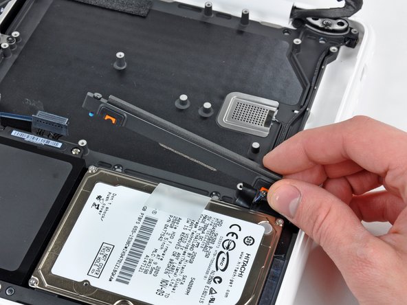
    • Lift the free side of the hard drive and pull it away from the side of the upper case.

    • The hard drive is still attached to the upper case by the hard drive cable.

  23. Este paso está sin traducir. Ayuda a traducirlo

    : paso 23, imagen 1 de 2 : paso 23, imagen 2 de 2
    • Disconnect the hard drive by pulling the hard drive cable connector away from its socket on the hard drive.

  24. Este paso está sin traducir. Ayuda a traducirlo

    : paso 24, imagen 1 de 2 : paso 24, imagen 2 de 2
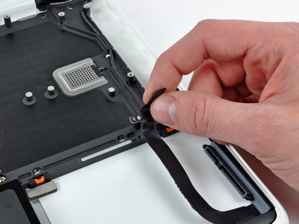
    • Remove the single 3.1 mm Phillips screw securing the hard drive cable to the upper case.

    • Lift the hard drive cable out of the upper case.

  25. Este paso está sin traducir. Ayuda a traducirlo

    : paso 25, imagen 1 de 1
    • Remove two 5 mm Tri-Wing screws securing the battery to the upper case near the battery connector.

  26. Este paso está sin traducir. Ayuda a traducirlo

    : paso 26, imagen 1 de 1
    • Use the tip of a spudger to carefully peel back the finger of the warning label to reveal a hidden Tri-Wing screw.

    • Remove the 5 mm Tri-Wing screw securing the battery to the upper case.

  27. Este paso está sin traducir. Ayuda a traducirlo

    : paso 27, imagen 1 de 1
    • Remove three 3.1 mm Phillips screws securing the battery near the edge of the upper case.

    • When reinstalling the battery, be sure to install these three screws before proceeding to fasten the Tri-Wing screws. Keep an eye on the keyboard ribbon cable, you may need to use the flat of the spudger to hold the ribbon cable out of the path of the battery as it swings down into place.

  28. Este paso está sin traducir. Ayuda a traducirlo

    : paso 28, imagen 1 de 1
    • Lift the battery near its connector and remove it from the upper case.

    • When replacing the battery, take care that the keyboard ribbon cable is not trapped underneath.

  29. Este paso está sin traducir. Ayuda a traducirlo

    : paso 29, imagen 1 de 3 : paso 29, imagen 2 de 3 : paso 29, imagen 3 de 3
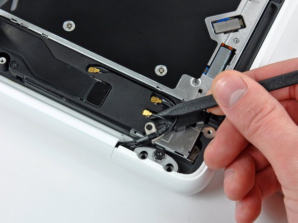
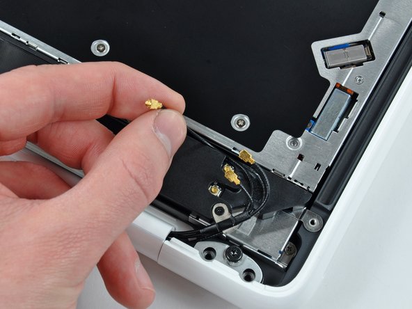
    • Use the tip of a spudger to pry the AirPort/Bluetooth antenna connectors (three total) up off the AirPort/Bluetooth board.

    • If necessary, de-route the long antenna cable from its slot in the rear speaker housing.

  30. Este paso está sin traducir. Ayuda a traducirlo

    : paso 30, imagen 1 de 1
    • Remove the single 3 mm Phillips screw securing the antenna ground straps to the rear speaker housing.

  31. Este paso está sin traducir. Ayuda a traducirlo

    : paso 31, imagen 1 de 1
    • Remove the single 2.2 mm Phillips screw inserted horizontally into the side of the optical drive.

  32. Este paso está sin traducir. Ayuda a traducirlo

    : paso 32, imagen 1 de 1
    • Remove the single 12 mm Phillips screw securing the rear speaker to the upper case.

  33. Este paso está sin traducir. Ayuda a traducirlo

    : paso 33, imagen 1 de 1
    • Remove the rear speaker assembly from your MacBook.

  34. Este paso está sin traducir. Ayuda a traducirlo

    : paso 34, imagen 1 de 1
    • Remove the single 4.5 mm Phillips screw securing the inner edge of the optical drive to the upper case.

  35. Este paso está sin traducir. Ayuda a traducirlo

    : paso 35, imagen 1 de 1
    • Remove the two 2.5 mm Phillips screws securing the optical drive to the upper case near the optical drive opening.

  36. Este paso está sin traducir. Ayuda a traducirlo

    : paso 36, imagen 1 de 1
    • Lift the optical drive near its connector and pull it away from the upper case to remove it from the computer.

  37. Este paso está sin traducir. Ayuda a traducirlo

    : paso 37, imagen 1 de 1
    • Open your MacBook so the display is perpendicular to the upper case.

    • Place your opened MacBook on a table as pictured.

    • While holding the display and upper case together with your left hand, remove the remaining T8 Torx screw from the lower display bracket.

    • Before retightening the T8 Torx screws, close the display and adjust it so that the back edges of the upper case and display are aligned and the gaps at the ends of the hinge are equal.

  38. Este paso está sin traducir. Ayuda a traducirlo

    : paso 38, imagen 1 de 1
    • Be sure to hold the display and upper case together with your left hand. Failure to do so may cause the freed display/upper case to fall, potentially damaging each component.

    • Remove the last remaining T8 Torx screw securing the display to the upper case.

  39. Este paso está sin traducir. Ayuda a traducirlo

    : paso 39, imagen 1 de 2 : paso 39, imagen 2 de 2
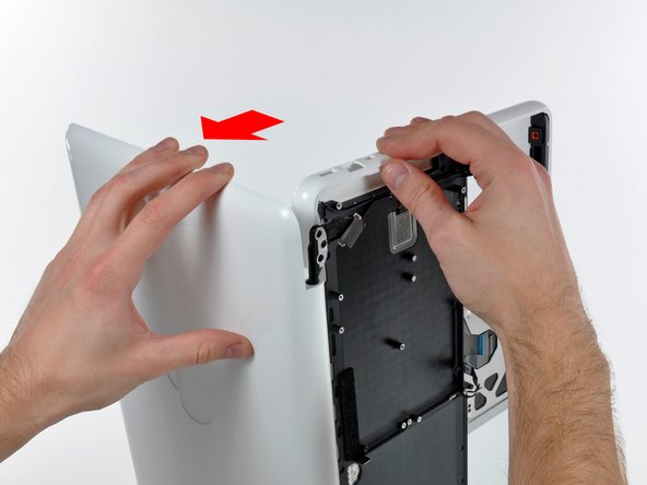
    • Grab the upper case with your right hand and rotate it slightly toward the top of the display so the upper display bracket clears the edge of the upper case.

    • The display data cable may cause the upper display bracket to get caught on the upper case. It may be helpful to slightly rotate the upper case away from the display for more clearance.

    • Rotate the display slightly away from the upper case.

  40. Este paso está sin traducir. Ayuda a traducirlo

    : paso 40, imagen 1 de 1
    • Lift the display up and away from the upper case, minding any brackets or cables that may get caught.

  41. Este paso está sin traducir. Ayuda a traducirlo

    : paso 41, imagen 1 de 3 : paso 41, imagen 2 de 3 : paso 41, imagen 3 de 3
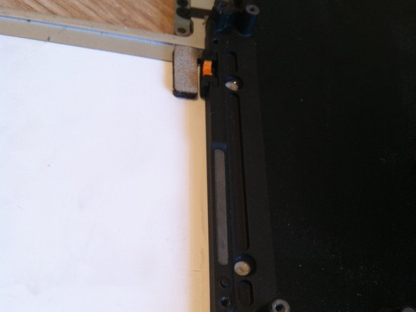
    • There are four orange and black rubber inserts that the hard drive sits in. One side has full circles and the other side has half circles. (The other side of the half circles are located on the hard drive bracket that was previously removed).

    • The new upper case may not have these inserts. Be sure to remove them from the old and insert into the new.

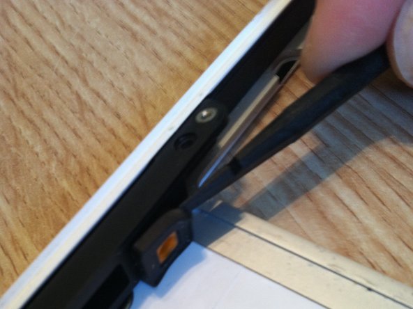
    • The inserts are easily pried out with a spudger or a flat tipped screwdriver. They are not glued in, but instead have notched sides to hold them in place.

  42. Este paso está sin traducir. Ayuda a traducirlo

    : paso 42, imagen 1 de 1
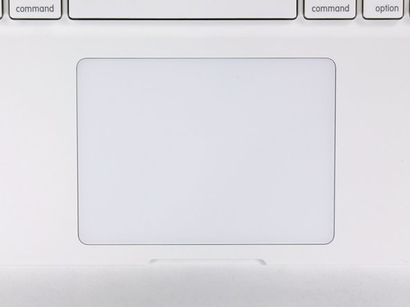
    • Remove the four 1.3 mm Phillips screws securing the upper edge of the trackpad to the upper case.

  43. Este paso está sin traducir. Ayuda a traducirlo

    : paso 43, imagen 1 de 1
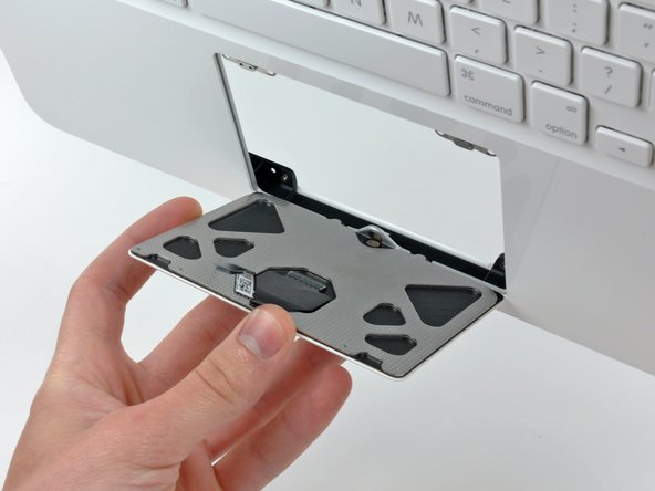
    • Carefully tilt the trackpad away from the keyboard side of the upper case.

    • Pull the trackpad away from its opening in the upper case to clear the two mounting tabs on its lower edge.

  44. Este paso está sin traducir. Ayuda a traducirlo

    : paso 44, imagen 1 de 1
    • Remove the 1 mm T6 Torx set screw near the front edge of the upper case.

  45. Este paso está sin traducir. Ayuda a traducirlo

    : paso 45, imagen 1 de 2 : paso 45, imagen 2 de 2
    • Use the following steps to install the old trackpad into your new upper case.

    • Reinstall the T6 Torx set screw until it is flush with the aluminum bracket surrounding the trackpad.

    • Place the trackpad back into its void in the upper case, being sure the lower tabs are inserted underneath the keyboard side of the upper case.

    • Be sure the trackpad ribbon cable is not pinched between the trackpad and the upper case.

  46. Este paso está sin traducir. Ayuda a traducirlo

    : paso 46, imagen 1 de 2 : paso 46, imagen 2 de 2
    • Reinstall the four silver Phillips screws securing the trackpad to its steel brackets.

    • Loosen all four silver screws about 1/16th of a turn.

    • Flip the upper case over and adjust the position of the trackpad until the gap between the trackpad and the upper case is evenly spaced around the perimeter of the trackpad.

    • Tighten the four silver screws to hold the trackpad in place.

    • Repeat this process until the trackpad is perfectly positioned in its void on the upper case.

  47. Este paso está sin traducir. Ayuda a traducirlo

    : paso 47, imagen 1 de 1
    • While repeatedly pressing the trackpad to simulate clicking, tighten the T6 Torx set screw until the trackpad no longer wiggles freely.

    • Do not over-tighten the set screw, as the button will cease to click at a certain point. Adjust the set screw until the movable side of the trackpad has minimal play.

Linea de Meta

197 personas más completaron esta guía.

25 comentarios

NOTE: Ensure you don't pull the entire assembly straight up or the base will come off the logic board. Use an extremely small straight blade screw drive to gently loosen the inside assembly while gently pulling on the wire bundle! Will save buying a new logic board!!!!

janesem - Contestar

Some of the screws are extremely tight, I stripped at least 6 Phillips screws during the upper case replacement.

firstn10 - Contestar

I used the iFixit 54 bit kit and found that the Phillips 000 bit fits the screws better than the recommended 00 bit. When loosening or tightening I use plenty of downward pressure to keep the bit from rising out of the screw head and damaging it. The torx screws are so much easier to work with and I wonder why they don't use only those.

Matthew Hester -

Definitely only use unworn, appropriately sized drivers when going into any Mac or iPhone. If the driver starts to slip, stop and access the situation. That said, I have encountered many screws with damaged screw heads. I usually first try the “rubber band” trick to loosen the ruined screw. If that doesn’t work, I often resort to using a dremel tool to cut a slot in the screw (while protecting everything from the debris generated). In all cases, be careful - one slip can do a lot of damage.

Lance J -

Great guide! My only comment would be to remove the battery first. It makes dealing with the keyboard ZIF cable much easier to install/remove.

sales - Contestar

Agregar Comentario

Ver Estadísticas:

Ultimas 24 horas: 2

Ultimos 7 días: 24

Ultimos 30 días: 96

Todo El Tiempo: 178,009