Esta versión puede contener ediciones incorrectas. Cambie a la última instantánea verificada.
Qué necesitas
-
-
Retira los diez tornillos que aseguran la carcasa inferior al ordenador:
-
Tres tornillos Phillips de 13.5 mm
-
Siete tornillos Phillips de 3 mm.
-
-
-
Si está presente, agarre la lengüeta de plástico unida al conector de la batería y tire de ella hacia el borde frontal del dispositivo. En los modelos Late-2011, el conector de la batería no tiene lengüeta y es simplemente un enchufe que se inserta directamente en la placa base.
-
-
Este paso está sin traducir. Ayuda a traducirlo
-
Use the flat end of a spudger to lift the right fan connector out of its socket on the logic board.
-
-
Este paso está sin traducir. Ayuda a traducirlo
-
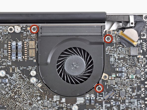
Remove the three 3.1 mm Phillips screws securing the right fan to the logic board.
-
-
Este paso está sin traducir. Ayuda a traducirlo
-
Remove the right fan from the upper case, minding its cable that may get caught.
-
-
Este paso está sin traducir. Ayuda a traducirlo
-
Use the flat end of a spudger to lift the left fan connector out of its socket on the logic board.
-
-
Este paso está sin traducir. Ayuda a traducirlo
-
Remove the three 3.1 mm Phillips screws securing the left fan to the logic board.
-
Remove the left fan from the upper case, minding its cable that may get caught.
-
-
Este paso está sin traducir. Ayuda a traducirlo
-
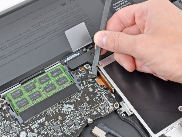
Use the tip of a spudger or your fingernail to flip up the retaining flap on the keyboard backlight ribbon cable.
-
Pull the keyboard backlight ribbon cable out of its socket.
-
-
Este paso está sin traducir. Ayuda a traducirlo
-
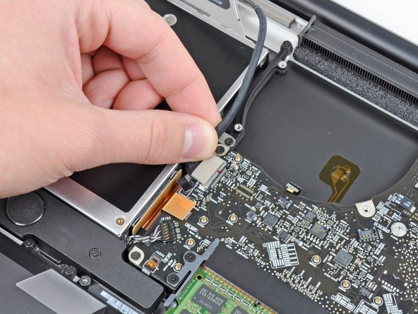
Use the tip of a spudger to push the small plastic cable retainer away from the camera cable socket for enough clearance to remove the camera cable.
-
-
Este paso está sin traducir. Ayuda a traducirlo
-
Pull the camera cable toward the optical drive opening to disconnect it from the logic board.
-
-
Este paso está sin traducir. Ayuda a traducirlo
-
Use the flat end of a spudger to pry the optical drive connector up and out of its socket on the logic board.
-
-
Este paso está sin traducir. Ayuda a traducirlo
-
Use the flat end of a spudger to lift the subwoofer & right speaker connector out of its socket on the logic board.
-
-
Este paso está sin traducir. Ayuda a traducirlo
-
Use the tip of a spudger or your fingernail to flip up the retaining flap on the IR sensor ribbon cable socket.
-
Pull the IR sensor ribbon cable out of its socket.
-
-
Este paso está sin traducir. Ayuda a traducirlo
-
Remove the following four screws:
-
Two 3.5 mm Phillips screws
-
Two 1.6 mm Phillips screws
-
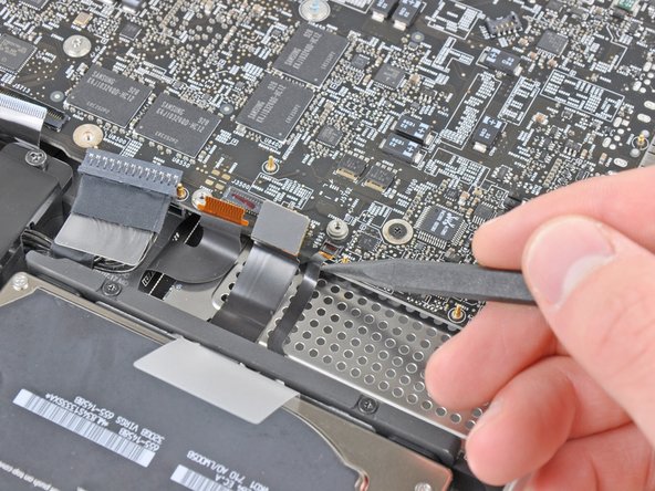
Remove both connector shields from the logic board.
-
-
Este paso está sin traducir. Ayuda a traducirlo
-
Use the flat end of a spudger to pry the trackpad connector up and out of its socket on the logic board.
-
-
-
Este paso está sin traducir. Ayuda a traducirlo
-
Use your fingernail to flip up the retaining flap on the keyboard ribbon cable socket.
-
Pull the keyboard ribbon cable out of its socket.
-
-
Este paso está sin traducir. Ayuda a traducirlo
-
Use your fingernail to flip up the retaining flap on the express card cage ribbon cable socket.
-
Pull the express card cage ribbon cable out of its socket.
-
-
Este paso está sin traducir. Ayuda a traducirlo
-
Use the flat end of a spudger to lift the hard drive cable connector up and out of its socket on the logic board.
-
-
Este paso está sin traducir. Ayuda a traducirlo
-
Use the tip of a spudger or your fingernail to flip up the retaining flap on the battery indicator cable socket.
-
Pull the battery indicator ribbon cable out of its socket.
-
-
Este paso está sin traducir. Ayuda a traducirlo
-
Lift the black plastic flap attached to the display data cable retainer and rotate it toward the DC-In side of the MacBook.
-
Pull the display data cable out of its socket.
-
-
Este paso está sin traducir. Ayuda a traducirlo
-
Remove the following eight screws securing the logic board and DC-In board to the upper case:
-
Six 3.2 mm Phillips screws
-
Two 7.6 mm Phillips screws
-
-
Este paso está sin traducir. Ayuda a traducirlo
-
Lift the logic board assembly from the side nearest the optical drive and lift it away from the upper case.
-
Carefully pull the ports and DC-In board away from the side of the upper case and remove the logic board assembly, minding any cables that may get caught.
-
-
Este paso está sin traducir. Ayuda a traducirlo
-
Remove the two Phillips screws securing the hard drive bracket to the upper case.
-
Remove the hard drive bracket from the upper case.
-
-
Este paso está sin traducir. Ayuda a traducirlo
-
Peel the hard drive and battery indicator cables off the adhesive securing them to the express card cage.
-
-
Este paso está sin traducir. Ayuda a traducirlo
-
Remove the following five screws securing the express card cage to the upper case:
-
Three 2 mm Phillips screws
-
Two 4 mm Phillips screws
-
-
Este paso está sin traducir. Ayuda a traducirlo
-
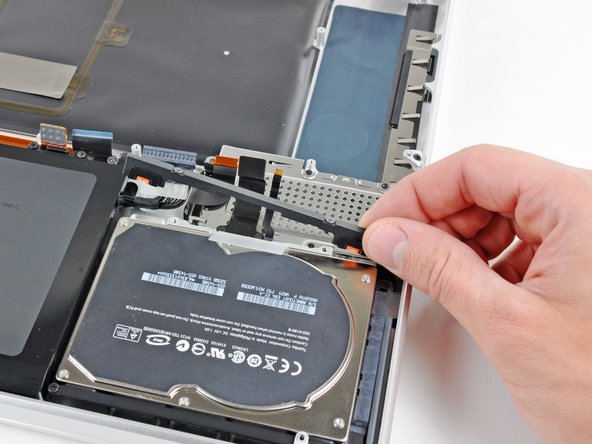
Using its attached pull tab, lift the hard drive out of the upper case.
-
-
Este paso está sin traducir. Ayuda a traducirlo
-
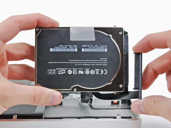
Pull the hard drive cable connector away from the body of the hard drive.
-
Remove the hard drive from the upper case and set it aside.
-
-
Este paso está sin traducir. Ayuda a traducirlo
-
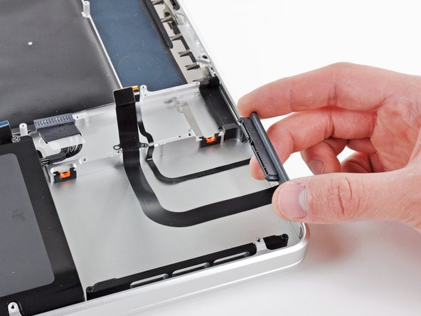
Remove the two 2.2 mm Phillips screws securing the hard drive cable to the upper case.
-
Remove the hard drive cable from the upper case.
-
-
Este paso está sin traducir. Ayuda a traducirlo
-
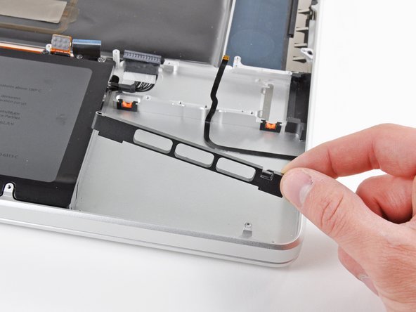
Remove the two 10 mm Phillips screws securing the front hard drive bracket to the upper case.
-
Remove the front hard drive bracket.
-
-
Este paso está sin traducir. Ayuda a traducirlo
-
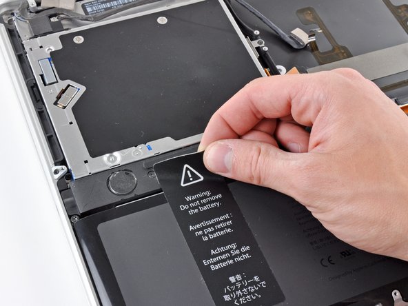
Use an iPod opening tool or another soft thin-edged tool to carefully lift up a corner of the "Warning: Do not remove the battery" sticker off the right speaker/subwoofer enclosure.
-
Peel the sticker off the right speaker/subwoofer enclosure.
-
-
Este paso está sin traducir. Ayuda a traducirlo
-
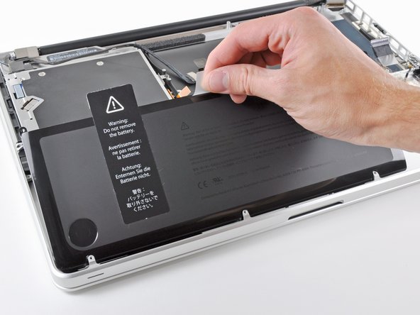
Remove the three 6.5 mm Tri-point screws securing the battery to the upper case.
-
Using its attached pull tab, lift the battery out of the upper case.
-
-
Este paso está sin traducir. Ayuda a traducirlo
-
Carefully disconnect the Bluetooth cable from the Bluetooth board.
-
-
Este paso está sin traducir. Ayuda a traducirlo
-
Use the flat end of a spudger to peel the thin plastic cover off the top and sides of the Bluetooth board housing.
-
-
Este paso está sin traducir. Ayuda a traducirlo
-
Use the flat end of a spudger to pry the Bluetooth antenna connector up and off its socket on the Bluetooth board.
-
-
Este paso está sin traducir. Ayuda a traducirlo
-
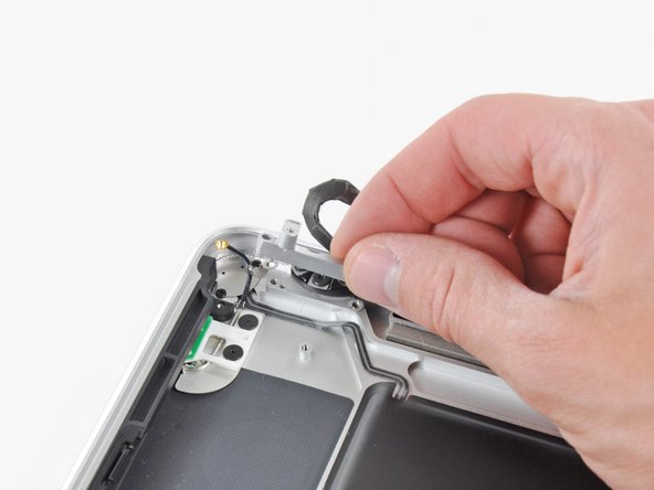
Remove the small piece of EMI foam attached near the Bluetooth board.
-
-
Este paso está sin traducir. Ayuda a traducirlo
-
Remove the three 3.5 mm Phillips screws securing the optical drive to the upper case.
-
-
Este paso está sin traducir. Ayuda a traducirlo
-
Remove the optical drive assembly from the upper case.
-
-
Este paso está sin traducir. Ayuda a traducirlo
-
Remove the following three screws securing the subwoofer & right speaker to the upper case:
-
One 2.6 mm Phillips screw
-
Two 12.3 mm Phillips screws
-
-
Este paso está sin traducir. Ayuda a traducirlo
-
Remove the subwoofer and right speaker assembly from the upper case.
-
-
Este paso está sin traducir. Ayuda a traducirlo
-
Remove the two 7.1 mm Phillips screws securing the camera cable retainer to the upper case.
-
Remove the camera cable retainer from the upper case.
-
-
Este paso está sin traducir. Ayuda a traducirlo
-
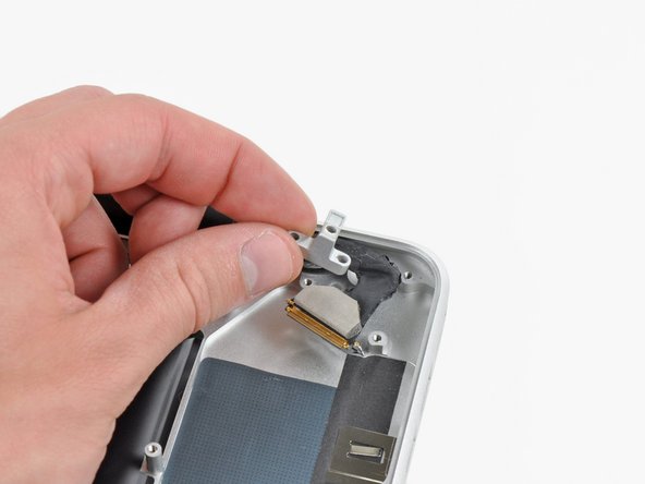
Remove the two 7.1 mm Phillips screws securing the display data cable retainer to the upper case.
-
Remove the display data cable retainer.
-
-
Este paso está sin traducir. Ayuda a traducirlo
-
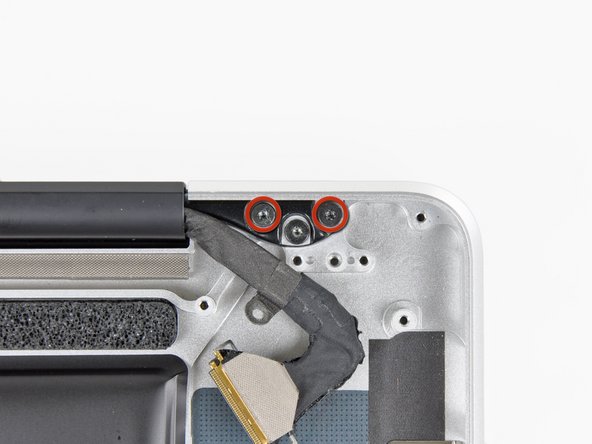
Remove the two outer 6.8 mm T6 Torx screws from each of the two display brackets (four screws total).
-
-
Este paso está sin traducir. Ayuda a traducirlo
-
While holding the display and upper case together with your left hand, remove the remaining T6 Torx screw from the lower display bracket.
-
-
Este paso está sin traducir. Ayuda a traducirlo
-
Remove the last remaining T6 Torx screw securing the display to the upper case.
-
-
Este paso está sin traducir. Ayuda a traducirlo
-
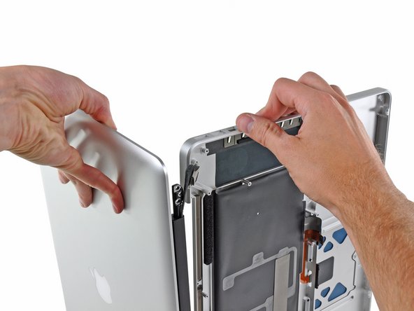
Grab the upper case with your right hand and rotate it slightly toward the top of the display so the upper display bracket clears the edge of the upper case.
-
Rotate the display slightly away from the upper case.
-
Lift the display up and away from the upper case, minding any brackets or cables that may get caught.
-


Cancelar: No complete esta guía.
45 personas más completaron esta guía.

4 comentarios
Is it possible to replace the keyboard?
Great guide! Although I don’t really look forward to replacing the upper case, BUT I will do so confidently thanks to Andrew’s instructions. This was needed because ½ of the backlight is not illuminating AND most importantly because my <right arrow> key stopped working. I saw how involved replacement of the keyboard assembly was and opted instead to replace the upper case with a used grade “A” upper case from a reputable seller.