Esta versión puede contener ediciones incorrectas. Cambiar a la última instantánea verificada.
Qué necesitas
-
-
Retira los diez tornillos que aseguran la carcasa inferior al ordenador:
-
Tres tornillos Phillips de 13.5 mm
-
Siete tornillos Phillips de 3 mm.
-
-
-
Si está presente, agarre la lengüeta de plástico unida al conector de la batería y tire de ella hacia el borde frontal del dispositivo. En los modelos Late-2011, el conector de la batería no tiene lengüeta y es simplemente un enchufe que se inserta directamente en la placa base.
-
-
Este paso está sin traducir. Ayuda a traducirlo
-
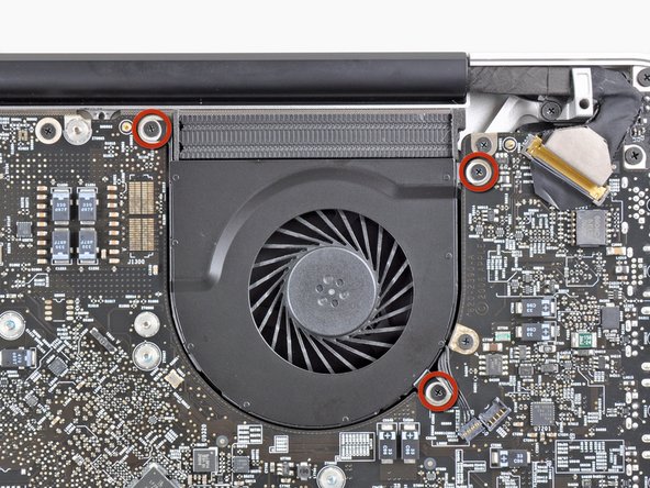
Use the flat end of a spudger to lift the right fan connector out of its socket on the logic board.
-
-
Este paso está sin traducir. Ayuda a traducirlo
-
Remove the three 3.1 mm Phillips screws securing the right fan to the logic board.
-
-
Este paso está sin traducir. Ayuda a traducirlo
-
Remove the right fan from the upper case, minding its cable that may get caught.
-
-
Este paso está sin traducir. Ayuda a traducirlo
-
Use the flat end of a spudger to lift the left fan connector out of its socket on the logic board.
-
-
Este paso está sin traducir. Ayuda a traducirlo
-
Remove the three 3.1 mm Phillips screws securing the left fan to the logic board.
-
Remove the left fan from the upper case, minding its cable that may get caught.
-
-
Este paso está sin traducir. Ayuda a traducirlo
-
Use the tip of a spudger or your fingernail to flip up the retaining flap on the keyboard backlight ribbon cable.
-
Pull the keyboard backlight ribbon cable out of its socket.
-
-
Este paso está sin traducir. Ayuda a traducirlo
-
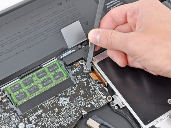
Use the tip of a spudger to push the small plastic cable retainer away from the camera cable socket for enough clearance to remove the camera cable.
-
-
-
Este paso está sin traducir. Ayuda a traducirlo
-
Pull the camera cable toward the optical drive opening to disconnect it from the logic board.
-
-
Este paso está sin traducir. Ayuda a traducirlo
-
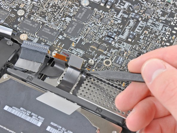
Use the flat end of a spudger to pry the optical drive connector up and out of its socket on the logic board.
-
-
Este paso está sin traducir. Ayuda a traducirlo
-
Use the flat end of a spudger to lift the subwoofer & right speaker connector out of its socket on the logic board.
-
-
Este paso está sin traducir. Ayuda a traducirlo
-
Use the tip of a spudger or your fingernail to flip up the retaining flap on the IR sensor ribbon cable socket.
-
Pull the IR sensor ribbon cable out of its socket.
-
-
Este paso está sin traducir. Ayuda a traducirlo
-
Remove the following four screws:
-
Two 3.5 mm Phillips screws
-
Two 1.6 mm Phillips screws
-
Remove both connector shields from the logic board.
-
-
Este paso está sin traducir. Ayuda a traducirlo
-
Use the flat end of a spudger to pry the trackpad connector up and out of its socket on the logic board.
-
-
Este paso está sin traducir. Ayuda a traducirlo
-
Use your fingernail to flip up the retaining flap on the keyboard ribbon cable socket.
-
Pull the keyboard ribbon cable out of its socket.
-
-
Este paso está sin traducir. Ayuda a traducirlo
-
Use your fingernail to flip up the retaining flap on the express card cage ribbon cable socket.
-
Pull the express card cage ribbon cable out of its socket.
-
-
Este paso está sin traducir. Ayuda a traducirlo
-
Use the flat end of a spudger to lift the hard drive cable connector up and out of its socket on the logic board.
-
-
Este paso está sin traducir. Ayuda a traducirlo
-
Use the tip of a spudger or your fingernail to flip up the retaining flap on the battery indicator cable socket.
-
Pull the battery indicator ribbon cable out of its socket.
-
-
Este paso está sin traducir. Ayuda a traducirlo
-
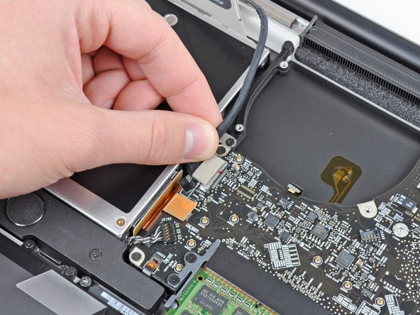
Lift the black plastic flap attached to the display data cable retainer and rotate it toward the DC-In side of the MacBook.
-
Pull the display data cable out of its socket.
-
-
Este paso está sin traducir. Ayuda a traducirlo
-
Remove the following eight screws securing the logic board and DC-In board to the upper case:
-
Six 3.2 mm Phillips screws
-
Two 7.6 mm Phillips screws
-
-
Este paso está sin traducir. Ayuda a traducirlo
-
Lift the logic board assembly from the side nearest the optical drive and lift it away from the upper case.
-
Carefully pull the ports and DC-In board away from the side of the upper case and remove the logic board assembly, minding any cables that may get caught.
-
-
Este paso está sin traducir. Ayuda a traducirlo
-
Remove the eight 8.3 mm Phillips screws securing the heat sink to the logic board.
-
-
Este paso está sin traducir. Ayuda a traducirlo
-
Squeeze the heat sink thermal sensor cable between your thumb and the tip of a spudger.
-
Lift the spudger upward to lift the thermal sensor connector out of its socket on the logic board.
-
-
Este paso está sin traducir. Ayuda a traducirlo
-
Pull the DC-In board connector out of its socket on the logic board.
-
-
Este paso está sin traducir. Ayuda a traducirlo
-
Remove the two 7.9 mm Phillips screws securing the left speaker to the logic board.
-
-
Este paso está sin traducir. Ayuda a traducirlo
-
Slightly lift the left speaker assembly away from the logic board.
-
Use the flat end of a spudger to lift the left speaker and microphone connectors out of their sockets on the logic board.
-
-
Este paso está sin traducir. Ayuda a traducirlo
-
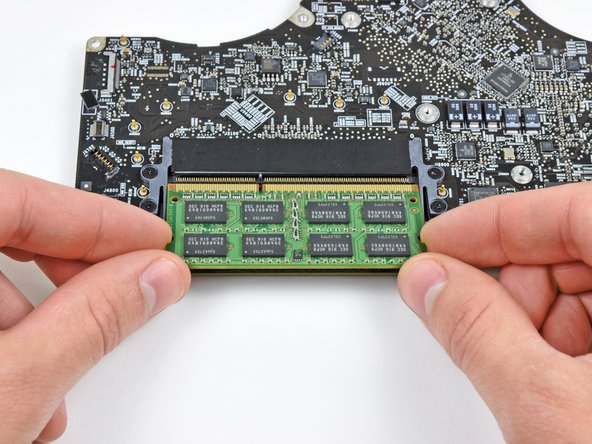
Release the tabs on each side of the RAM chip by simultaneously pushing each tab away from the RAM.
-
After the RAM chip has popped up, pull it straight out of its socket.
-
Logic board remains.
-


Cancelar: No complete esta guía.
99 personas más completaron esta guía.

13 comentarios
Good question! We’ve had good quality Ethernet cables easily slip out of the jacks on several of our MacBook Pros (and TiBook) over the years.
hi Andrew... My macbook pro retina.. When starting up, the progress bar gors slow, then macbook suddenly shuts down.. But before that, there is a grain/noise of rainbow colors across the hole screen showing up.. .. Do you regocnize the problem and what can it be, the graphic / logic card?
Thank you.