Esta versión puede contener ediciones incorrectas. Cambie a la última instantánea verificada.
Qué necesitas
-
-
Remueve los siguientes diez tornillos que sujetan la caja inferior de la caja a la caja superior:
-
Siete tornillos Phillips de 3 mm.
-
Tres tornillos Phillips de 13.5 mm.
-
-
ComprarHerramienta utilizada en este paso:P6 Pentalobe Screwdriver 2009 15" MacBook Pro Battery$5.49
-
Retira los dos tornillos de Pentalobe de 5 puntos a lo largo del borde superior de la batería.
-
-
Este paso está sin traducir. Ayuda a traducirlo
-
Use a spudger to pry the fan connector straight up off the logic board.
-
-
Este paso está sin traducir. Ayuda a traducirlo
-
Remove the three T6 Torx screws securing the left fan to the logic board.
-
Lift the fan out of the upper case.
-
-
Este paso está sin traducir. Ayuda a traducirlo
-
Use the flat end of a spudger to disconnect the left fan connector from the logic board.
-
-
Este paso está sin traducir. Ayuda a traducirlo
-
Remove the three T6 Torx screws securing the left fan to the logic board.
-
Lift the left fan out of the upper case.
-
-
-
Este paso está sin traducir. Ayuda a traducirlo
-
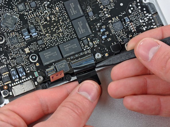
Hold the end of the cable retainer down with one finger while you use the tip of a spudger to slightly lift the other end and rotate it away from the camera cable connector.
-
Disconnect the camera cable by pulling the male end straight away from its socket.
-
-
Este paso está sin traducir. Ayuda a traducirlo
-
Disconnect the camera cable by pulling the male end straight away from its socket.
-
-
Este paso está sin traducir. Ayuda a traducirlo
-
Use the flat end of a spudger to pry the optical drive cable connector up off the logic board.
-
-
Este paso está sin traducir. Ayuda a traducirlo
-
Using the flat end of a spudger, pry the subwoofer connector straight up from the connector jack.
-
-
Este paso está sin traducir. Ayuda a traducirlo
-
Use the flat end of a spudger to pry the hard drive/IR sensor cable connector up off the logic board.
-
-
Este paso está sin traducir. Ayuda a traducirlo
-
Remove the two 1.5 mm Phillips screws securing the cable cover to the logic board.
-
Lift the cable cover out of the upper case.
-
-
Este paso está sin traducir. Ayuda a traducirlo
-
Use a spudger to pry the trackpad flex ribbon cable connector up off the logic board.
-
-
Este paso está sin traducir. Ayuda a traducirlo
-
Use your fingernail to flip up the locking flap on the ZIF socket for the keyboard ribbon cable. The locking flap is located at the opposite side of the socket compared to the keyboard ribbon cable. Hook your fingernail under it and carefully lift it up vertically.
-
Use the tip of a spudger to slide the keyboard ribbon cable out of its socket.
-
-
Este paso está sin traducir. Ayuda a traducirlo
-
Use a spudger to pry the battery indicator ribbon cable connector up off the logic board.
-
-
Este paso está sin traducir. Ayuda a traducirlo
-
Remove the single 7 mm Phillips screw securing the display data cable retainer to the upper case.
-
Remove the display data cable retainer from the upper case.
-
-
Este paso está sin traducir. Ayuda a traducirlo
-
Grab the plastic pull tab secured to the display data cable lock and rotate it toward the DC-in side of the computer.
-
-
Este paso está sin traducir. Ayuda a traducirlo
-
Pull the display data cable connector straight away from its socket.
-
-
Este paso está sin traducir. Ayuda a traducirlo
-
Using the tip of a spudger, flip up the keyboard backlight ribbon cable retaining flap.
-
Pull the keyboard backlight ribbon cable straight out of its socket.
-
-
Este paso está sin traducir. Ayuda a traducirlo
-
Remove the following screws:
-
Seven 3.3 mm T6 Torx screws securing the logic board to the upper case.
-
Two 8 mm T6 Torx screws securing the DC-In board to the upper case.
-
-
Este paso está sin traducir. Ayuda a traducirlo
-
Carefully lift the logic board assembly from the left side and work it out of the upper case, minding the port side that may get caught during removal.
-
-
Este paso está sin traducir. Ayuda a traducirlo
-
Lift the logic board enough to gain clearance and use a spudger to pry the microphone up off the upper case.
-
Slide the logic board away from the port openings and lift the assembly out of the upper case.
-
-
Este paso está sin traducir. Ayuda a traducirlo
-
Slide the logic board away from the port openings and lift the assembly out of the upper case.
-
-
Este paso está sin traducir. Ayuda a traducirlo
-
Lay the logic board on a soft flat surface with the heat sink facing up.
-
Disconnect the DC-In Board connector from the logic board by pulling it straight away from its socket.
-


Cancelar: No complete esta guía.
22 personas más completaron esta guía.

11 comentarios
Great guide. The locking flaps in Steps 18, 21 and 23 are a little hard to decipher in the pictures. I accidentally pulled out the keyboard ribbon cable without unlocking its retaining flap, but I apparently got it in back correctly (after lifting the flap) and didn't break anything because everything works now. This has solved the charging problems I've had for years. I should be able to get a couple more useful years out of this machine now.
Great guide. For my Mid 2009 Macbook Pro, I only had one fan, so didn't have to do step 9 and 10. Also in Step 24 I had 8 3.3mm T6 Torx, not 7. Other than that was perfect!
How long did it take you Anonymous 7084?
Very good guide. It worked out perfectly for me. It takes around 45 minutes to complete.
Question: In My late model 2011 MacBook Pro is the pin port replaceable? The actual pins? It looks from the photo (step 28) as though it is adhered to the board. The receiving pins in the port in my Notebook are burning away and charging plug contact is greatly affected.