Esta versión puede contener ediciones incorrectas. Cambie a la última instantánea verificada.
Qué necesitas
-
-
Remueve los siguientes diez tornillos que aseguran la cubierta trasera a la cubierta superior.
-
Tres tornillos tipo Philips (punta cruz) de 13.5 mm (14.1 mm)
-
Cuando remuevas estos tornillos, ten en cuenta cómo salen en un ángulo ligero. Deben volverse a instalar de igual forma.
-
-
-
Usa el borde del spudger para apalancar el conector de la batería hacia arriba del enchufe en la tarjeta lógica.
-
-
-
Remueve los dos tornillos Tri-point de 7.4 mm que sujetan la batería a la caja superior.
-
-
-
Despega con cuidado el extremo redondeado de la etiqueta de advertencia de la batería (el que no tiene pegamento) de la carcasa superior situada entre la batería y la unidad óptica para descubrir un tornillo Tri-point adicional.
-
Remueve el último tornillo de tres puntos Y0 de 7.4 mm que sujeta la batería a la caja superior.
-
-
-
Usa la lengüeta de plástico conectada para remover la batería de la caja trasera.
-
Cárgala al 100 % y luego sigue cargándola durante al menos 2 horas. Luego, desenchúfala y úsala para drenar la batería. Cuando veas la advertencia de batería baja, guarda tu trabajo y mantén tu computadora portátil encendida hasta que se apague por batería baja. Espera al menos cinco horas, luego carga tu portátil ininterrumpidamente hasta 100%.
-
Si notas algún comportamiento inusual o problemas luego de instalar tu batería nueva, podría necesitar restablecer el controlador de gestión de sistema de tu MacBook.
-
-
-
Remueve los tres tornillos de torsión T6 de 3.4 mm (3.1 mm) que aseguran el disipador izquierdo a la tarjeta madre
-
-
Este paso está sin traducir. Ayuda a traducirlo
-
Use the flat end of a spudger to lift the right fan connector out of its socket on the logic board.
-
-
-
Este paso está sin traducir. Ayuda a traducirlo
-
Remove the three 3.4 mm (3.1 mm) T6 Torx screws securing the right fan to the logic board.
-
Lift the right fan out of its opening in the logic board.
-
-
Este paso está sin traducir. Ayuda a traducirlo
-
Pull the camera cable out of its socket on the logic board.
-
-
Este paso está sin traducir. Ayuda a traducirlo
-
Use the flat end of a spudger to pry the AirPort/Bluetooth connector up from its socket on the logic board.
-
-
Este paso está sin traducir. Ayuda a traducirlo
-
Use the flat end of a spudger to lift the optical drive connector out of its socket on the logic board.
-
-
Este paso está sin traducir. Ayuda a traducirlo
-
Disconnect the hard drive/IR sensor cable from its socket on the logic board by lifting up from beneath its connector.
-
-
Este paso está sin traducir. Ayuda a traducirlo
-
Use the flat end of a spudger to lift the subwoofer/right speaker connector out of its socket on the logic board.
-
-
Este paso está sin traducir. Ayuda a traducirlo
-
Use the flat end of a spudger to pry the trackpad connector up and out of its socket on the logic board.
-
-
Este paso está sin traducir. Ayuda a traducirlo
-
Use your fingernail to flip up the retaining flap on the keyboard ribbon cable ZIF socket.
-
Use the tip of a spudger to pull the keyboard ribbon cable out of its socket.
-
-
Este paso está sin traducir. Ayuda a traducirlo
-
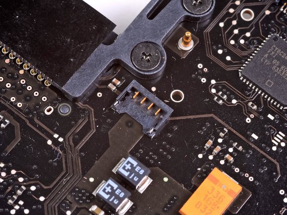
Use the flat end of a spudger to lift the battery indicator connector up and out of its socket on the logic board.
-
-
Este paso está sin traducir. Ayuda a traducirlo
-
Grab the plastic pull tab secured to the display data cable lock and rotate it toward the DC-In side of the computer.
-
Pull the display data cable straight out of its socket on the logic board.
-
-
Este paso está sin traducir. Ayuda a traducirlo
-
Use the tip of a spudger to flip up the retaining flap on the keyboard backlight ribbon cable ZIF socket.
-
Pull the keyboard backlight ribbon cable out of its socket.
-
-
Este paso está sin traducir. Ayuda a traducirlo
-
Remove the following nine screws:
-
Seven 3.4 mm ( 3.1 mm) T6 Torx screws on the logic board
-
Two 8 mm T6 Torx screws on the DC-In board
-
-
Este paso está sin traducir. Ayuda a traducirlo
-
Carefully lift the logic board assembly from its left side and work it out of the upper case, minding the optical drive cable and the I/O ports that may get caught during removal.
-
If necessary, use the flat end of a spudger to separate the microphone from the upper case.
-
Pull the I/O port side of the logic board away from the side of the upper case and remove the logic board assembly.
-
-
Este paso está sin traducir. Ayuda a traducirlo
-
Remove the six #1 Phillips screws securing the heat sink to the logic board.
-
-
-
Suelte las pestañas en cada lado del chip RAM al empujar simultáneamente cada pestaña de la memoria RAM.
-
Estas pestañas bloquean el chip en su lugar y su liberación hará que el chip "salte".
-
Repita este proceso si hay un segundo chip RAM instalado.
-
La placa lógica permanece. Si necesita volver a colocar el disipador de calor en la placa lógica, tenemos unaguía de pasta térmicaque facilita el reemplazo del compuesto térmico.
-


Cancelar: No complete esta guía.
148 personas más completaron esta guía.

30 comentarios
Can the CPU replaced on this Logic Board? Or I have to replace the whole Logic Board?!
Logic board completely
gzasuwa -
cpu is part of board
Hello. Why don't you remove RAM in the beginning? Thanks