Esta versión puede contener ediciones incorrectas. Cambie a la última instantánea verificada.
Qué necesitas
-
-
Retira los siguientes diez tornillos que fijan la caja inferior a la superior:
-
Siete tornillos Phillips de 3 mm.
-
Tres tornillos Phillips de 13.5 mm.
-
-
-
Tres tornillos Pentalobe aseguran la batería a la carcasa superior. Se pueden eliminar con este destornillador especial.
-
-
-
Inclina la batería hacia atrás lo suficiente para acceder al conector del cable de la batería.
-
Extrae el conector del cable de la batería de su zócalo en la placa lógica y extrae la batería de la caja superior.
-
Si estás instalando una batería nueva, debes calibrarla tan pronto como sea posible.
-
-
Este paso está sin traducir. Ayuda a traducirlo
-
Use the flat end of a spudger to pry the fan cable connector up off its socket on the logic board.
-
-
Este paso está sin traducir. Ayuda a traducirlo
-
Remove the three identical T6 Torx screws securing the fan to the upper case.
-
-
-
Este paso está sin traducir. Ayuda a traducirlo
-
Hold the end of the cable retainer down with one finger while you use the tip of a spudger to slightly lift the other end and rotate it away from the camera cable connector.
-
-
Este paso está sin traducir. Ayuda a traducirlo
-
Disconnect the camera cable by pulling the male end straight away from its socket.
-
-
Este paso está sin traducir. Ayuda a traducirlo
-
Use the flat end of a spudger to pry the optical drive cable connector up off the logic board.
-
-
Este paso está sin traducir. Ayuda a traducirlo
-
Using the flat end of a spudger, pry the subwoofer connector straight up off the logic board.
-
-
Este paso está sin traducir. Ayuda a traducirlo
-
Use the flat end of a spudger to pry the hard drive/IR sensor cable connector up off the logic board.
-
-
Este paso está sin traducir. Ayuda a traducirlo
-
Remove the two 1.5 mm Phillips screws securing the cable cover to the logic board.
-
Lift the cable cover out of the upper case.
-
-
Este paso está sin traducir. Ayuda a traducirlo
-
Use a spudger to pry the trackpad flex ribbon cable connector up off the logic board.
-
-
Este paso está sin traducir. Ayuda a traducirlo
-
Using the tip of a spudger, flip up the keyboard ribbon cable retaining flap.
-
Pull the keyboard ribbon cable straight out of its socket.
-
-
Este paso está sin traducir. Ayuda a traducirlo
-
Use a spudger to pry the battery indicator ribbon cable connector up off the logic board.
-
-
Este paso está sin traducir. Ayuda a traducirlo
-
Remove the single 7 mm Phillips screw securing the display data cable retainer to the upper case.
-
Remove the display data cable retainer from the upper case.
-
-
Este paso está sin traducir. Ayuda a traducirlo
-
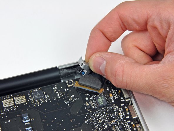
Grab the plastic pull tab secured to the display data cable lock and rotate it toward the DC-in side of the computer.
-
Pull the display data cable connector straight away from its socket.
-
-
Este paso está sin traducir. Ayuda a traducirlo
-
Using the tip of a spudger, flip up the keyboard backlight ribbon cable retaining flap.
-
Pull the keyboard backlight ribbon cable straight out of its socket.
-
-
Este paso está sin traducir. Ayuda a traducirlo
-
Remove the following screws:
-
Eight 3.5 mm T6 Torx screws securing the logic board to the upper case.
-
Two T6 Torx screws securing the DC-In board to the upper case.
-
-
Este paso está sin traducir. Ayuda a traducirlo
-
Carefully lift the logic board assembly from the left side and work it out of the upper case, minding the port side that may get caught during removal.
-
-
Este paso está sin traducir. Ayuda a traducirlo
-
Lift the logic board enough to gain clearance and use a spudger to pry the microphone up off the upper case.
-
Slide the logic board away from the port openings and lift the assembly out of the upper case.
-
-
Este paso está sin traducir. Ayuda a traducirlo
-
Use the flat end of a spudger to pry the left speaker connector up off the logic board.
-
-
Este paso está sin traducir. Ayuda a traducirlo
-
Remove the two 5 mm Phillips screws securing the left speaker to the logic board assembly.
-
If necessary, use a spudger to lift the microphone out of its housing in the left speaker.
-
-
Este paso está sin traducir. Ayuda a traducirlo
-
Lift the left speaker assembly out of the logic board.
-


Cancelar: No complete esta guía.
4 personas más completaron esta guía.
