Esta versión puede contener ediciones incorrectas. Cambie a la última instantánea verificada.
Qué necesitas
-
-
Retira los siguientes diez tornillos que fijan la caja inferior a la superior:
-
Siete tornillos Phillips de 3 mm.
-
Tres tornillos Phillips de 13.5 mm.
-
-
-
Tres tornillos Pentalobe aseguran la batería a la carcasa superior. Se pueden eliminar con este destornillador especial.
-
-
-
Inclina la batería hacia atrás lo suficiente para acceder al conector del cable de la batería.
-
Extrae el conector del cable de la batería de su zócalo en la placa lógica y extrae la batería de la caja superior.
-
Si estás instalando una batería nueva, debes calibrarla tan pronto como sea posible.
-
-
Este paso está sin traducir. Ayuda a traducirlo
-
Use the flat end of a spudger to pry the fan cable connector up off its socket on the logic board.
-
-
Este paso está sin traducir. Ayuda a traducirlo
-
Remove the three identical T6 Torx screws securing the fan to the upper case.
-
-
-
Este paso está sin traducir. Ayuda a traducirlo
-
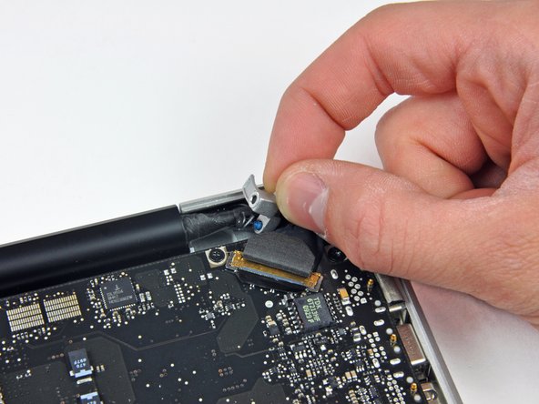
Hold the end of the cable retainer down with one finger while you use the tip of a spudger to slightly lift the other end and rotate it away from the camera cable connector.
-
-
Este paso está sin traducir. Ayuda a traducirlo
-
Disconnect the camera cable by pulling the male end straight away from its socket.
-
-
Este paso está sin traducir. Ayuda a traducirlo
-
Use the flat end of a spudger to pry the optical drive cable connector up off the logic board.
-
-
Este paso está sin traducir. Ayuda a traducirlo
-
Using the flat end of a spudger, pry the subwoofer connector straight up off the logic board.
-
-
Este paso está sin traducir. Ayuda a traducirlo
-
Use the flat end of a spudger to pry the hard drive/IR sensor cable connector up off the logic board.
-
-
Este paso está sin traducir. Ayuda a traducirlo
-
Remove the two 1.5 mm Phillips screws securing the cable cover to the logic board.
-
Lift the cable cover out of the upper case.
-
-
Este paso está sin traducir. Ayuda a traducirlo
-
Use a spudger to pry the trackpad flex ribbon cable connector up off the logic board.
-
-
Este paso está sin traducir. Ayuda a traducirlo
-
Using the tip of a spudger, flip up the keyboard ribbon cable retaining flap.
-
Pull the keyboard ribbon cable straight out of its socket.
-
-
Este paso está sin traducir. Ayuda a traducirlo
-
Use a spudger to pry the battery indicator ribbon cable connector up off the logic board.
-
-
Este paso está sin traducir. Ayuda a traducirlo
-
Remove the single 7 mm Phillips screw securing the display data cable retainer to the upper case.
-
Remove the display data cable retainer from the upper case.
-
-
Este paso está sin traducir. Ayuda a traducirlo
-
Grab the plastic pull tab secured to the display data cable lock and rotate it toward the DC-in side of the computer.
-
Pull the display data cable connector straight away from its socket.
-
-
Este paso está sin traducir. Ayuda a traducirlo
-
Using the tip of a spudger, flip up the keyboard backlight ribbon cable retaining flap.
-
Pull the keyboard backlight ribbon cable straight out of its socket.
-
-
Este paso está sin traducir. Ayuda a traducirlo
-
Remove the following screws:
-
Eight 3.5 mm T6 Torx screws securing the logic board to the upper case.
-
Two T6 Torx screws securing the DC-In board to the upper case.
-
-
Este paso está sin traducir. Ayuda a traducirlo
-
Carefully lift the logic board assembly from the left side and work it out of the upper case, minding the port side that may get caught during removal.
-
-
Este paso está sin traducir. Ayuda a traducirlo
-
Lift the logic board enough to gain clearance and use a spudger to pry the microphone up off the upper case.
-
Slide the logic board away from the port openings and lift the assembly out of the upper case.
-
-
Este paso está sin traducir. Ayuda a traducirlo
-
Remove six Phillips screws securing the heat sink to the logic board.
-


Cancelar: No complete esta guía.
15 personas más completaron esta guía.

2 comentarios
Hey ifixit, I really appreciate the level of description to your various guides. I was following this guide to a tee except that I couldn't find my spudger, but managed with using creditcard like. I was following this guide as I want to change the thermal paste. I completed step 23, but from there on it was a bust, it felt way too tight when I was trying too lift the logic board, I could only get i a few centimeters up on the left side. It felt stuck at the bottom/uppercase. i checked that all screws and connections were free and I couldn't find any obstacles, but didn't want to use force lifting it. should it be easy/hard to lift??
To answer Mike’s question (although 4 years late, I hope this helps others), when I disassembled my 2009 15” MacBook Pro I had to use more force than I would have liked when removing the Logic Board, it turns out that one of the heatsinks has some adhesive on it that sticks to the keyboard, and you have to break it apart. So more force than you’ll probably be comfortable with is required.