Esta versión puede contener ediciones incorrectas. Cambiar a la última instantánea verificada.
Qué necesitas
-
-
Utiliza los dedos para empujar las dos lengüetas de liberación de la batería y sácala del ordenador.
-
-
-
Retira los dos tornillos Phillips de 2,8 mm en el compartimento de la batería cerca del pestillo.
-
-
-
Levanta la parte trasera de la caja y desliza los dedos por los laterales, liberando la caja a medida que avanzas. Una vez que hayas liberado los laterales, es posible que tengas que mover la caja hacia arriba y hacia abajo para liberar la parte delantera de la caja superior (hay algunos clips de plástico ocultos que hay que quitar).
-
-
Este paso está sin traducir. Ayuda a traducirlo
-
Disconnect the orange SuperDrive ribbon cable from the logic board, removing tape as necessary.
-
-
Este paso está sin traducir. Ayuda a traducirlo
-
Remove the following 4 screws:
-
Two 3.3 mm silver Phillips screws on either side of the SuperDrive.
-
One 4.7 mm silver T6 Torx screw from the top left corner of the drive
-
One 6.2 mm black Phillips screw at the top right corner of the drive.
-
-
Este paso está sin traducir. Ayuda a traducirlo
-
Disconnect the hard drive and ExpressCard connectors from the left side of the logic board.
-
-
Este paso está sin traducir. Ayuda a traducirlo
-
Disconnect the iSight and display data cables from the logic board by sliding the cables out of their connectors, removing tape as necessary.
-
-
Este paso está sin traducir. Ayuda a traducirlo
-
Disconnect the eight indicated connectors by placing a spudger beneath each cable and lifting up.
-
-
-
Este paso está sin traducir. Ayuda a traducirlo
-
Remove the silver T6 Torx screw securing the ground loop in the display data cable to the casing.
-
-
Este paso está sin traducir. Ayuda a traducirlo
-
Remove the single T6 Torx screw securing the clear plastic shield over the right ambient light sensor.
-
Lift the clear plastic shield off the right ambient light sensor.
-
-
Este paso está sin traducir. Ayuda a traducirlo
-
Peel up the orange Kapton tape securing the right thermal sensor cable to the logic board.
-
-
Este paso está sin traducir. Ayuda a traducirlo
-
Remove the following 15 screws:
-
One 4.4 mm black Phillips screw to the right of the ram slot.
-
Eight 4.7 mm silver T6 Torx screws securing the logic board to the lower case.
-
One 6.2 mm black T6 Torx screw on the right side of the left fan.
-
Five 9.4 mm silver T6 Torx screws securing the left and right fans.
-
-
Este paso está sin traducir. Ayuda a traducirlo
-
Hold the logic board down with one hand and use your other hand to lift the left fan up from its housing. There is a piece of black tape securing the fan to the heat sink. Carefully peel this tape up from the heat sink as you lift the fan up.
-
Place the fan above the Airport card. It is not necessary to remove the fan from the computer entirely.
-
-
Este paso está sin traducir. Ayuda a traducirlo
-
Lift the right fan up and carefully peel up the tape securing the fan to the heat sink as you go.
-
Remove the right fan from the computer.
-
-
Este paso está sin traducir. Ayuda a traducirlo
-
Lift up the left side of the logic board and disconnect the gray and black power cable from the bottom of the board.
-
-
Este paso está sin traducir. Ayuda a traducirlo
-
Grasp the logic board at the left side and at the thin section, and rotate the logic board out of the lower case.
-
-
Este paso está sin traducir. Ayuda a traducirlo
-
Peel up the left ambient light sensor cable from above the left fan, removing tape as necessary.
-
Remove the left fan from the computer.
-
-
Este paso está sin traducir. Ayuda a traducirlo
-
Disconnect the three antenna cables attached to the Airport Extreme card.
-
-
Este paso está sin traducir. Ayuda a traducirlo
-
Deroute the Airport antenna cables from their channel in the left speaker.
-
-
Este paso está sin traducir. Ayuda a traducirlo
-
Remove the single black T6 Torx screw located just above the Airport Extreme card.
-
Lift the small silver metal retaining bracket up and out of the computer.
-
-
Este paso está sin traducir. Ayuda a traducirlo
-
Lift the Airport Extreme card up and slide it out of its connector.
-
-
Este paso está sin traducir. Ayuda a traducirlo
-
Peel up the orange hard drive cable from above the ExpressCard cage.
-
-
Este paso está sin traducir. Ayuda a traducirlo
-
Disconnect the speaker cable from the corner of the left I/O board.
-
-
Este paso está sin traducir. Ayuda a traducirlo
-
Carefully peel up the black adhesive tape securing the speaker cable along the rear edge of the lower case.
-
-
Este paso está sin traducir. Ayuda a traducirlo
-
Continue to free the speaker cable from the black tape until it is free from all three sections of tape.
-
-
Este paso está sin traducir. Ayuda a traducirlo
-
Remove the single black T6 Torx screw securing the right speaker to the lower case.
-
-
Este paso está sin traducir. Ayuda a traducirlo
-
Use a spudger to pry up the right speaker from the lower case.
-
Remove the speakers from the computer.
-
-
Este paso está sin traducir. Ayuda a traducirlo
-
Support the display with one hand while removing the following 3 screws:
-
Two 9.5 mm silver T6 Torx screws with threads on only part of the shaft on the inside of the display hinges.
-
One 9.5 mm silver T6 Torx screw with threads on the entire shaft on the outside of the left hinge.
-
-
Este paso está sin traducir. Ayuda a traducirlo
-
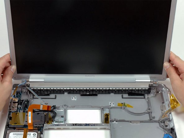
Grasp the display assembly on both sides and lift it up and out of the computer.
-
-
Este paso está sin traducir. Ayuda a traducirlo
-
Disconnect the IR and sleep light cables from their connectors above the hard drive.
-
-
Este paso está sin traducir. Ayuda a traducirlo
-
Remove the two silver Phillips screws securing the hard drive retaining bracket to the lower case.
-
Lift the hard drive retaining bracket up and out of the computer.
-
-
Este paso está sin traducir. Ayuda a traducirlo
-
Lift the hard drive up from the right side and remove it and the attached cable from the computer.
-
-
Este paso está sin traducir. Ayuda a traducirlo
-
Remove the following 7 screws/standoffs:
-
Four black T6 Torx screws securing the left I/O board to the lower case.
-
Two silver T6 Torx screws securing the battery connector to the lower case.
-
One 4 mm standoff located between the audio jacks.
-
-
Este paso está sin traducir. Ayuda a traducirlo
-
Lift the left I/O board up from the right side and slide it out of the computer.
-
-
Este paso está sin traducir. Ayuda a traducirlo
-
Peel up the orange Kapton tape covering the right thermal sensor.
-
Use a spudger to pry the right thermal sensor off the lower case.
-
-
Este paso está sin traducir. Ayuda a traducirlo
-
Use a spudger to pry up the PRAM battery off the lower case.
-


Cancelar: No complete esta guía.
19 personas más completaron esta guía.
