Esta versión puede contener ediciones incorrectas. Cambie a la última instantánea verificada.
Qué necesitas
-
-
Utiliza una moneda o un spudger para girar el tornillo de bloqueo de la batería 90 grados en el sentido de las agujas del reloj.
-
-
-
Desatornilla los tres tornillos Phillips espaciados uniformemente a lo largo de la pared posterior del compartimento de la batería.
-
-
-
Retira los 3 tornillos siguientes:
-
Un Phillips#00 de 11 mm en el centro de la caja inferior. (Cabeza: 5 mm de diámetro x 0,75 mm de grosor)
-
Dos Phillips #00 de 14,5 mm (cabeza: 5 mm de diámetro x 0,75 mm de grosor)
-
-
-
Retira los siguientes 4 tornillos de la parte posterior del ordenador:
-
Dos Phillips #00 de 11 mm, con mango (2,2 mm de diámetro x 2 mm de longitud) (Cabeza: 3,2 mm de diámetro x 0,5 mm de grosor)
-
Dos Phillips #00 de 7,25 mm, con mango (2 mm de diámetro x 3,75 mm de longitud) (cabeza: 3,2 mm de diámetro x 0,5 mm de grosor)
-
-
-
Utiliza una herramienta de apertura de plástico, un crédito de plástico caducado o una tarjeta de grosor similar para hacer palanca en la carcasa superior, comenzando en la esquina superior izquierda y trabajando alrededor de la parte frontal del ordenador.
-
-
-
Sujeta la lengüeta de plástico blanca unida al disco duro y tire de ella hacia la izquierda, extrayendo el disco duro del ordenador.
-
-
-
-
Retira el tornillo Phillips #00 de 2 mm que sujeta la esquina posterior de la unidad óptica.
-
Es posible que el cable Bluetooth con cubierta plateada esté tapando el tornillo. Si es así, empújalo con cuidado hacia un lado. Es posible que tengas que quitar el tornillo que sujeta las orejetas de blindaje de tierra para los dos cables cercanos antes de que pueda mover el cable Bluetooth a un lado lo suficiente.
-
Este tornillo es de 7 mm en los modelos anteriores, y puede ser de 4,2 mm en los modelos Santa Rosa/Penryn y 2009.
-
-
-
Levanta el lado de la unidad óptica más cercano a usted y, a continuación, desliza la unidad hacia usted, hacia arriba y fuera del ordenador.
-
En primer lugar, desliza su lado más cercano a la parte posterior del Macbook por debajo del borde del marco posterior a la izquierda de la bisagra, mientras desliza también la pestaña de montaje de la unidad óptica en su esquina superior izquierda por debajo de los cables en esta ubicación.
-
Baja la unidad parcialmente hasta el alojamiento inferior. Manten el cable del disco duro alejado de la bahía de la unidad óptica.
-
Antes de colocar la unidad por completo en su sitio, utiliza un destornillador para empujar hacia delante (hacia la parte delantera de la unidad) el orificio del tornillo de la lengüeta de montaje de la unidad.
-
Empuja hacia adelante el deslizador, que se extiende a lo largo del lado más alejado de la unidad, para insertar el extremo de este deslizador en un pequeño canal del marco de la carcasa inferior. Esto ayuda a mantener la unidad en su lugar.
-
-
Este paso está sin traducir. Ayuda a traducirlo
-
For original Macbook Core Duo and Core 2 Duo models, remove these 3 screws:
-
Two 3 mm Phillips near the right speaker.
-
One 6 mm Phillips threaded through a hole in a plastic finger above the subwoofer.
-
For Santa Rosa/Penryn and 2009 models, which don't have a c-channel:
-
Remove only the single 3 mm Phillips screw from the right speaker, and skip step 26.
-
-
Este paso está sin traducir. Ayuda a traducirlo
-
Lift the right speaker out of its housing and set it to the side.
-
-
Este paso está sin traducir. Ayuda a traducirlo
-
Using a spudger, gently pry up the white plastic slot and slide the metal c-channel to the right and away from the display.
-
-
Este paso está sin traducir. Ayuda a traducirlo
-
Use a spudger to carefully disconnect the microphone cable from the logic board. You'll want to work from side to side, and slowly wiggle the plug back and out of its socket.
-
-
Este paso está sin traducir. Ayuda a traducirlo
-
Lift up on the black right speaker cable with one hand, and deroute the microphone cable from the silver metal clip just above the right RAM slot.
-
-
Este paso está sin traducir. Ayuda a traducirlo
-
If you didn't remove the ground lug retaining screw in step 20 above, remove it now. It's a 7mm (may be 4mm or 3mm in Santa Rosa/Penryn and 2009 models) Phillips screw securing the ground lugs on the right speaker cable and microphone cable to the metal frame.
-
-
Este paso está sin traducir. Ayuda a traducirlo
-
Deroute the microphone cable and the black display data cable from the tabs at the bottom of the subwoofer.
-
-
Este paso está sin traducir. Ayuda a traducirlo
-
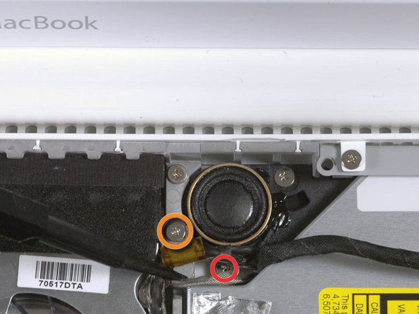
Remove the single 3 mm Phillips screw securing the ground lug in the display data cable located just above the Bluetooth board. This screw may also be securing a ground lug in the speaker cable.
-
-
Este paso está sin traducir. Ayuda a traducirlo
-
Disconnect the antenna cables from the Airport card:
-
If you have an original MacBook Core Duo or Core 2 Duo model, see the first picture, which shows that there are three antenna cables.
-
If you have a MacBook Core 2 Duo Santa Rosa/Penryn or 2009 model, there are only two antenna cables, and the plug/socket for the black inverter cable is in a different location. There may be a square foam piece over the plug/socket for the inverter board connector.
-
Disconnect the inverter cable from its socket by inserting a spudger between the right or left ends of the plug and the socket, and prying gently vertically. Do NOT pry up on the socket--you must pull up on the plug alone, vertically out of the socket. Do not pull in the direction of the cable wires or you will tear the socket off the logic board.
-
-
Este paso está sin traducir. Ayuda a traducirlo
-
For original Macbook Core Duo and Core 2 Duo models, see first picture and remove the following 2 screws from the right hinge mount:
-
One 6 mm Phillips on the left side of the hinge mount.
-
One 10 mm Phillips on the right side of the hinge mount.
-
For Santa Rosa/Penryn and 2009 models, see second picture and remove the following 3 screws from the right hinge mount:
-
One 3 mm smalller diameter Phillips on the far left.
-
One 5.2 mm larger diameter, 4.2 mm head Phillips in the middle.
-
One 10 mm larger diameter, 4.2mm head Phillips from the far right.
-
Before removing the right hinge mount, take care to see how its pieces fit together, including the small white plastic piece. Knowing how the mount pieces fit together will help with reassembly. Lift the right hinge mount with the small white plastic piece out of the computer.
-
-
Este paso está sin traducir. Ayuda a traducirlo
-
Hold the display with one hand while removing the following 3 screws from the left hinge mount:
-
One 7.2 mm smaller diameter Phillips from the right side.
-
One 5.2 mm larger diameter Phillips from the middle.
-
One larger diameter 10 mm Phillips from the left side.
-
Lift the left hinge mount with white plastic piece out of the computer.
-
Check that the cables coming out of the right end of the left hinge are not trapped under other cables.
-
-
Este paso está sin traducir. Ayuda a traducirlo
-
Grasp the display assembly on either side and lift it up and out of the computer, taking care that the cables attached to the display don't snag on parts in the lower case.
-
-
Este paso está sin traducir. Ayuda a traducirlo
-
Use a thin plastic card to release the tabs and their clips holding the front display bezel to the display assembly. There are five tabs along the left side of the display bezel.
-
-
Este paso está sin traducir. Ayuda a traducirlo
-
Continue to free the tabs along the the top edge of the display assembly.
-
-
Este paso está sin traducir. Ayuda a traducirlo
-
Next, free the five tabs securing the display bezel on the right side.
-
-
Este paso está sin traducir. Ayuda a traducirlo
-
Lift up the front display bezel from the top and use your plastic card to free the tabs along the bottom edge of the display bezel.
-
After freeing all holding tabs, lift the front display bezel away from the display assembly.
-
-
Este paso está sin traducir. Ayuda a traducirlo
-
Use a metal spudger or another thin tool to carefully pry the gray plastic clips off the tabs molded into the front display bezel. A 0.8mm flat screwdriver may be useful for this step. You may find that it's easier to remove some of these clips by prying up on their long sides.
-
-
Este paso está sin traducir. Ayuda a traducirlo
-
Insert one end of the retaining clip beneath the edge of its recess cut into the LCD bracket.
-
Use the edge of a spudger to push the short hook tab on the underside of the other end of the retaining clip into the recess cut into the LCD bracket.
-


Cancelar: No complete esta guía.
73 personas más completaron esta guía.

9 comentarios
One only needs to go to page 14 of this guide to install a new front bezel. This can be replaced without virtually dismantling the entire computer. By that, I mean you don't have to take the battery out, you don't have to take the top of the case off, you don't have to take the entire display off. Simply pry off the old front bezel with a plastic card, just as in the directions, being careful not to overextend the display on its hinges while in the processes.
There is really no need to disassemble the bottom of the computer and remove the display assembly from the bottom case to replace the display bezel. You can simply start at step 36 if you only want to remove/replace the bezel. (MB062LL/A)
Can you please guys confirm that it is possible to replace display bezel without having to dissamble topcase, optical drive, etc? Should I just go to Step 36 and go on? Is that easy?
Yang -
I too have confirmed that you can simply start at step 36 if you only want to remove/replace the bezel.