Saltar al contenido principal

MacBook Air 13" Early 2014 Logic Board Replacement

Qué necesitas

  1. MacBook Air 13" Early 2014 Logic Board Replacement, Lower Case: paso 1, imagen 1 de 1
    Herramienta utilizada en este paso:
    P5 Pentalobe Screwdriver Retina MacBook Pro and Air
    $5.99
    Comprar
    • Before proceeding, power down your MacBook. Close the display and lay it on a soft surface, top-side down.

    • Use a P5 Pentalobe driver to remove ten screws securing the lower case, of the following lengths:

    • Two 9 mm screws

    • Eight 2.6 mm screws

  2. MacBook Air 13" Early 2014 Logic Board Replacement: paso 2, imagen 1 de 1
    • Wedge your fingers between the display and the lower case and pull upward to pop the lower case off the Air.

    • Remove the lower case and set it aside.

  3. MacBook Air 13" Early 2014 Logic Board Replacement, Battery Connector: paso 3, imagen 1 de 2 MacBook Air 13" Early 2014 Logic Board Replacement, Battery Connector: paso 3, imagen 2 de 2
    • To ensure that everything is de-energized and won't turn on while you're working, it is recommended that you disconnect the battery.

    • Grab the clear plastic pull tab attached to the battery connector and pull it parallel to the board toward the front edge of the Air.

    • Do not lift upward on the connector as you disconnect it or you risk damage to the connector socket.

  4. MacBook Air 13" Early 2014 Logic Board Replacement, I/O Board Cable: paso 4, imagen 1 de 1
    • Use the flat end of a spudger to pry the I/O board cable connector up out of its socket on the I/O board.

  5. MacBook Air 13" Early 2014 Logic Board Replacement: paso 5, imagen 1 de 1
    • Carefully peel the I/O board cable from the adhesive securing it to the top of the fan.

    • During reassembly, make sure this cable is in the correct orientation. It will fit if reversed, but the laptop will not boot.

  6. MacBook Air 13" Early 2014 Logic Board Replacement: paso 6, imagen 1 de 2 MacBook Air 13" Early 2014 Logic Board Replacement: paso 6, imagen 2 de 2
    • The following connector has an especially deep socket. Use care when disconnecting it.

    • While gently pulling the I/O board cable upward near its connection to the logic board, use the flat end of a spudger to pry up on alternating sides of the connector to help "walk" it out of its socket.

    • Remove the I/O board cable.

  7. MacBook Air 13" Early 2014 Logic Board Replacement, Fan: paso 7, imagen 1 de 1
    • Use the tip of a spudger to carefully flip up the retaining flap on the fan cable ZIF socket.

    • Be sure you are prying up on the hinged retaining flap, not the socket itself.

  8. MacBook Air 13" Early 2014 Logic Board Replacement: paso 8, imagen 1 de 1
    • Peel the rubber gasket off the adhesive on the top of the fan.

  9. MacBook Air 13" Early 2014 Logic Board Replacement: paso 9, imagen 1 de 1
    • Remove the following three screws securing the fan to the upper case:

    • One 3.6 mm T5 Torx screw

    • One 2.7 mm T5 Torx screw

    • One 3.6 mm T5 Torx screw with a short head

  10. MacBook Air 13" Early 2014 Logic Board Replacement: paso 10, imagen 1 de 2 MacBook Air 13" Early 2014 Logic Board Replacement: paso 10, imagen 2 de 2
    • Lift the fan from the I/O board side and pull it free from the upper case.

    • Removing the fan will also disconnect the fan ribbon cable. Be careful not to snag it.

  11. MacBook Air 13" Early 2014 Logic Board Replacement, I/O Board: paso 11, imagen 1 de 1
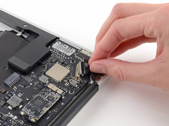
    • Disconnect the I/O board by pulling its power cable away from its socket on the logic board.

    • Pull the cable parallel to the face of the logic board toward the right edge of the Air.

  12. MacBook Air 13" Early 2014 Logic Board Replacement: paso 12, imagen 1 de 2 MacBook Air 13" Early 2014 Logic Board Replacement: paso 12, imagen 2 de 2
    • Use the flat end of a spudger to pry the left speaker cable connector up and out of its socket on the I/O board.

    • Pry up from beneath the wires.

  13. MacBook Air 13" Early 2014 Logic Board Replacement: paso 13, imagen 1 de 2 MacBook Air 13" Early 2014 Logic Board Replacement: paso 13, imagen 2 de 2
    • Use the tip of a spudger to carefully flip up the retaining flap on the microphone ribbon cable ZIF socket.

    • Make sure you are flipping up the retaining flap, not the socket itself.

  14. MacBook Air 13" Early 2014 Logic Board Replacement: paso 14, imagen 1 de 1
    • Remove the single 3.6 mm T5 Torx screw securing the I/O board to the upper case.

  15. MacBook Air 13" Early 2014 Logic Board Replacement: paso 15, imagen 1 de 2 MacBook Air 13" Early 2014 Logic Board Replacement: paso 15, imagen 2 de 2
    • Gently de-route the camera cable from its notch on the I/O board and push it out of the way with the tip of a spudger.

  16. MacBook Air 13" Early 2014 Logic Board Replacement: paso 16, imagen 1 de 1
    • Lift the I/O board from the logic board side and pull it free from the upper case.

    • Removing the I/O board will also disconnect the microphone ribbon cable. Be careful not to snag it.

  17. MacBook Air 13" Early 2014 Logic Board Replacement, Battery: paso 17, imagen 1 de 1
    • Remove the following five screws securing the battery to the upper case:

    • Three 6.3 mm T5 Torx screws

    • Two 2.4 mm T5 Torx screws

  18. MacBook Air 13" Early 2014 Logic Board Replacement: paso 18, imagen 1 de 1
    • When handling the battery, avoid squeezing or touching the four exposed lithium polymer cells.

    • Lift the battery from its edge nearest the logic board and remove it from the upper case.

  19. MacBook Air 13" Early 2014 Logic Board Replacement, Logic Board Assembly: paso 19, imagen 1 de 2 MacBook Air 13" Early 2014 Logic Board Replacement, Logic Board Assembly: paso 19, imagen 2 de 2
    • Grab the plastic pull tab secured to the display data cable lock and rotate it towards the top side of the computer.

  20. MacBook Air 13" Early 2014 Logic Board Replacement: paso 20, imagen 1 de 2 MacBook Air 13" Early 2014 Logic Board Replacement: paso 20, imagen 2 de 2
    • Pull the display data cable connector straight away from its socket.

    • Make sure to pull the connector parallel to the logic board, do not lift straight up from its socket.

  21. MacBook Air 13" Early 2014 Logic Board Replacement: paso 21, imagen 1 de 2 MacBook Air 13" Early 2014 Logic Board Replacement: paso 21, imagen 2 de 2
    • Use the flat end of a spudger to pry both antenna cable connectors up and off their sockets on the AirPort/Bluetooth card.

  22. MacBook Air 13" Early 2014 Logic Board Replacement: paso 22, imagen 1 de 2 MacBook Air 13" Early 2014 Logic Board Replacement: paso 22, imagen 2 de 2
    • Disconnect the camera cable connector with the tip of a spudger.

    • Push first on one side of the connector, then on the other side to carefully "walk" it out of its socket.

    • Pull the camera cable parallel to the face of the I/O board toward the front edge of the Air to disconnect it from its socket.

    • Do not lift upward on this cable as you disconnect it, as its socket may break off the logic board.

  23. MacBook Air 13" Early 2014 Logic Board Replacement: paso 23, imagen 1 de 2 MacBook Air 13" Early 2014 Logic Board Replacement: paso 23, imagen 2 de 2
    • Use the tip of a spudger or your fingernail to flip up the retaining flap on the trackpad ribbon cable ZIF socket.

    • Be sure you are prying up on the hinged retaining flap, not the socket itself.

    • Pull the trackpad ribbon cable straight out of its socket toward the front edge of the Air.

  24. MacBook Air 13" Early 2014 Logic Board Replacement: paso 24, imagen 1 de 3 MacBook Air 13" Early 2014 Logic Board Replacement: paso 24, imagen 2 de 3 MacBook Air 13" Early 2014 Logic Board Replacement: paso 24, imagen 3 de 3
    • Use the tip of a spudger to flip up the retaining flap on the keyboard backlight ribbon cable ZIF socket.

    • Be sure you are prying up on the hinged retaining flap, not the socket itself.

    • Use your spudger to gently pull the keyboard backlight ribbon cable out of its socket.

  25. MacBook Air 13" Early 2014 Logic Board Replacement: paso 25, imagen 1 de 1
    • Use the flat end of a spudger to pry the right speaker cable connector up and out of its socket on the logic board.

    • It is recommended to pry up from beneath the cables.

  26. MacBook Air 13" Early 2014 Logic Board Replacement: paso 26, imagen 1 de 1
    • Remove the six 6.3 mm T5 Torx screws securing the logic board to the upper case.

    • On some models these may be 4.1 mm T5 Torx screws.

  27. MacBook Air 13" Early 2014 Logic Board Replacement: paso 27, imagen 1 de 1
    • Remove the inner two 4.9 mm T8 Torx screws securing the antenna cable retainer and left clutch hinge to the upper case.

  28. MacBook Air 13" Early 2014 Logic Board Replacement: paso 28, imagen 1 de 1
    • Push the antenna cable retainer away slightly and remove the 3 mm T5 Torx screw securing the end of the heat sink to the upper case.

  29. MacBook Air 13" Early 2014 Logic Board Replacement: paso 29, imagen 1 de 3 MacBook Air 13" Early 2014 Logic Board Replacement: paso 29, imagen 2 de 3 MacBook Air 13" Early 2014 Logic Board Replacement: paso 29, imagen 3 de 3
    • Slide the flat end of a spudger under the right speaker from the end nearest the hinge to the front edge of the Air to loosen the adhesive.

    • Remove the right speaker from the upper case.

  30. MacBook Air 13" Early 2014 Logic Board Replacement: paso 30, imagen 1 de 2 MacBook Air 13" Early 2014 Logic Board Replacement: paso 30, imagen 2 de 2
    • Carefully remove the logic board assembly from the upper case, minding any cables that may get caught.

    • During reassembly:

    • Keep loose cables clear of the board so they aren't caught under it.

    • Make sure the antenna cables are inserted into their respective notches, as highlighted in the second picture.

  31. MacBook Air 13" Early 2014 Logic Board Replacement, Logic Board: paso 31, imagen 1 de 1
    • Remove the single 2.85 mm T5 Torx screw securing the SSD to the logic board.

  32. MacBook Air 13" Early 2014 Logic Board Replacement: paso 32, imagen 1 de 2 MacBook Air 13" Early 2014 Logic Board Replacement: paso 32, imagen 2 de 2
    • To avoid damaging its socket, do not lift the end of the SSD excessively.

    • Pull the drive straight out of its socket and remove it from the logic board.

    • When reinstalling the SSD, be sure it is properly seated before reinstalling its retaining screw.

  33. MacBook Air 13" Early 2014 Logic Board Replacement: paso 33, imagen 1 de 1
    • Remove the single 2.9 mm T5 Torx screw securing the AirPort/Bluetooth board to the logic board.

  34. MacBook Air 13" Early 2014 Logic Board Replacement: paso 34, imagen 1 de 2 MacBook Air 13" Early 2014 Logic Board Replacement: paso 34, imagen 2 de 2
    • To avoid damaging its socket, do not lift the end of the AirPort/Bluetooth board excessively.

    • Slightly lift the free end of the AirPort/Bluetooth board and pull it out of its socket on the logic board.

    • Remove the AirPort/Bluetooth board from the logic board.

  35. MacBook Air 13" Early 2014 Logic Board Replacement: paso 35, imagen 1 de 1
    • Remove the four 2.5 mm T5 Torx screws securing the heat sink to the logic board.

  36. MacBook Air 13" Early 2014 Logic Board Replacement: paso 36, imagen 1 de 2 MacBook Air 13" Early 2014 Logic Board Replacement: paso 36, imagen 2 de 2
    • If the heat sink seems to be stuck to the logic board after removing all four screws, use a spudger to carefully separate the heat sink from the faces of the CPU and GPU.

    • Remove the heat sink from the logic board.

    • When reinstalling the heat sink, be sure to apply a new layer of thermal paste. If you have never applied thermal paste before, we have a guide that makes it easy.

  37. MacBook Air 13" Early 2014 Logic Board Replacement: paso 37, imagen 1 de 3 MacBook Air 13" Early 2014 Logic Board Replacement: paso 37, imagen 2 de 3 MacBook Air 13" Early 2014 Logic Board Replacement: paso 37, imagen 3 de 3
    • When reassembling your device, be sure the heat sink's rubber gasket is installed correctly. The nub on the gasket should mate with the hole cut into the logic board near the heat sink fins.

    • The tail of the gasket should fit into the notch in the heat sink, it should not end up underneath the heat sink tab that will rest on the logic board.

    • Make sure the antenna cables are inserted into their respective notches on the logic board, as highlighted in the last picture.

Conclusión

To reassemble your device, follow these instructions in reverse order.

62 personas más completaron esta guía.

Jeff Suovanen

Miembro Desde 08/06/13

426,551 Reputación

259 Guías creadas

Equipo

iFixit Miembro de iFixit

Staff

135 Miembros

16,476 Guías creadas

5 comentarios

Easy peasy macbook squeezy.

The guide is very detailed, sometimes overcareful, but its completely ok because the delicate.

I personally skip some last steps because it wasn't necessary, but I recommend those with less experience to stick the guide.

Good luck to further readers.

alexxsanchezm - Contestar

I’m getting ready to replace the logic board on an early 2014 MacBook Air. I’m assuming that upgrading from the base i5 to an i7 8GB logic board at this time requires nothing more than the board replacement. Can anyone confirm this?

cwnoel - Contestar

Am also trying to replace an early 2014 i5 4GB to i7 8GB and need some answers. Will a 2014 i7 be compatible with a 2014 i5?

Samson Kissa - Contestar

CWNOEL or SAMSON KISSA, did you guy end up upgrading to i7 8 GB? is it possible?

Jayjay - Contestar

im trying to repair a female connector on the pcb/logic boad that the Li-battery cable plugs into. can anyone tell me where i can find female connector

358MA so i can attempt to solder it back onto the pcb board and continue my repair process and procedures. Thanks.

Theon - Contestar

Agregar Comentario

Ver Estadísticas:

Ultimas 24 horas: 7

Ultimos 7 días: 26

Ultimos 30 días: 143

Todo El Tiempo: 75,241