Esta versión puede contener ediciones incorrectas. Cambie a la última instantánea verificada.
Qué necesitas
-
-
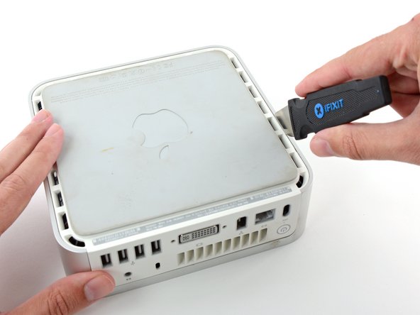
Apaga el Mac mini, desconecta todos los cables y dale la vuelta.
-
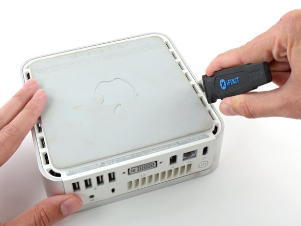
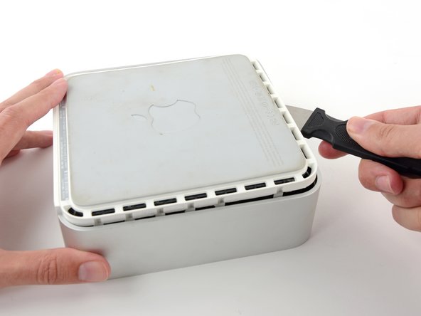
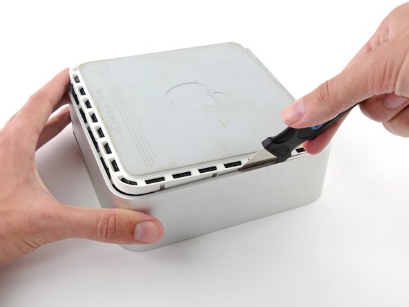
Inserta el Jimmy en la grieta entre la carcasa superior de aluminio y la carcasa inferior de plástico.
-
Insertar traducción aquí
-
-
Este paso está sin traducir. Ayuda a traducirlo
-
Grasp the Airport antenna board and lift it off of the two plastic posts holding it in place. You may need to push back the black plastic tab jutting through the lower left corner of the board.
-
-
Este paso está sin traducir. Ayuda a traducirlo
-
Remove the yellow tape securing the power button cable to the black plastic framework.
-
-
-
Este paso está sin traducir. Ayuda a traducirlo
-
Remove the three black Phillips screws securing the plastic framework to the logic board and lower case.
-
-
Este paso está sin traducir. Ayuda a traducirlo
-
Grasp the optical drive and mass storage unit in one hand and lift up enough so that you can see beneath it.
-
-
Este paso está sin traducir. Ayuda a traducirlo
-
With your free hand, pull the Bluetooth cable up from Bluetooth board and unplug the Airport antenna cable from the right of the Airport card. Caution: both of these connections are very small. When re-assembling unit after repair, you may want to remove the two screws holding the airport card to the assembly and lift the card up and out to re-attach the cables.
-
-
Este paso está sin traducir. Ayuda a traducirlo
-
Remove the two silver Phillips screws from the corners of the modem board.
-
-
Este paso está sin traducir. Ayuda a traducirlo
-
Pull the modem up from its connector. If it sticks, just wiggle it back and forth a bit as you pull up.
-
-
Este paso está sin traducir. Ayuda a traducirlo
-
Disconnect the RJ-11 cable from the back of the modem.
-
-
Este paso está sin traducir. Ayuda a traducirlo
-
Remove the two silver Phillips screws from the corners of the wireless interface board.
-
-
Este paso está sin traducir. Ayuda a traducirlo
-
Grasp the board at the front and back, and lift up on the front until the board pulls free of its connector.
-
-
Este paso está sin traducir. Ayuda a traducirlo
-
Pull back the black plastic latches on either end of the RAM chip.
-
-
Este paso está sin traducir. Ayuda a traducirlo
-
Grasp the RAM chip at the end opposite of the back ports, and pull directly up.
-
-
Este paso está sin traducir. Ayuda a traducirlo
-
Push the PRAM battery in and pull it up. You'll have to push the battery in further than you'd expect in order to get it to pop free.
-
-
Este paso está sin traducir. Ayuda a traducirlo
-
Disconnect the power button and sleep light cables from the logic board.
-
-
Este paso está sin traducir. Ayuda a traducirlo
-
Remove the single black Phillips screw from the front left corner of the logic board.
-
-
Este paso está sin traducir. Ayuda a traducirlo
-
Use one hand to slide a spudger underneath the logic board and the other to pull back on the black sleep light unit. Lift up the with the spudger to free the logic board from the lower case and use both hands to slide the logic board toward you.
-


Cancelar: No complete esta guía.
12 personas más completaron esta guía.
Documentos Adjuntos

3 comentarios
You are supposed to replace the heat transfer pad on the bottom case when you remove the logic board. If this pad doesn’t make good contact with the GPU, you’ll get overheating and the unit will goto sleep after a short time.
My Mac Mini G4 is missing the screws for the HDD/DVD carrier and the one screw for the logic board. Can you tell me where I can buy these or give me specs so I can find replacements on eBay?