Esta versión puede contener ediciones incorrectas. Cambie a la última instantánea verificada.
Qué necesitas
-
Este paso está sin traducir. Ayuda a traducirlo
-
Break the two warranty stickers by poking a screwdriver through them or peeling them off.
-
Remove the following twenty screws by rotating the screwdriver counterclockwise:
-
Eight 16.2mm Phillips #2 screws
-
Eight 15mm Phillips #2 screws
-
Four 19.1mm Phillips #2 screws
-
-
Este paso está sin traducir. Ayuda a traducirlo
-
Use a nylon spudger to pry the metal handle away from the outer shell.
-
Rotate the metal handle toward the center of the hoverboard to unlock the plate from the retaining clips.
-
Lift the hoverboard off the metal handle.
-
Repeat for the handle on the other side of the hoverboard.
-
-
-
Este paso está sin traducir. Ayuda a traducirlo
-
Lift the plastic cover on each side up and away from the device.
-
-
Este paso está sin traducir. Ayuda a traducirlo
-
Disconnect the following wires by pinching the connector tabs and pulling the plugs out of the connectors:
-
Charging port wires
-
Speaker assembly wires
-
Power button wires
-
Headlight wires
-
-
Este paso está sin traducir. Ayuda a traducirlo
-
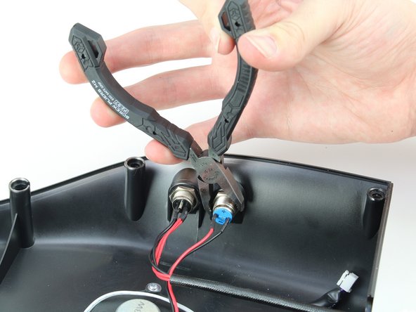
Peel off the glue around the power button.
-
Unscrew the hexagonal nut around the power button by rotating the nut counterclockwise with a pair of pliers.
-
-
Este paso está sin traducir. Ayuda a traducirlo
-
Feed the wire and connector through the removed nut and pull the power button out through the hole in the outer casing.
-


Cancelar: No complete esta guía.
Una persona más ha completado esta guía.

Equipo

Cal Poly, Team S15-G1, White Fall 2018 Miembro de Cal Poly, Team S15-G1, White Fall 2018
CPSU-WHITE-F18S15G1
4 Miembros
7 Guías creadas