Esta versión puede contener ediciones incorrectas. Cambie a la última instantánea verificada.
Qué necesitas
-
Este paso está sin traducir. Ayuda a traducirlo
-
Remove the faceplate by carefully prying around the edge using a plastic opening tool. Loosen the clips on the edge, then pull the faceplate off.
-
Use the tweezers to lift the faceplate from the rest of the device.
-
-
Este paso está sin traducir. Ayuda a traducirlo
-
Using a #00 Phillips head screwdriver, remove the following screws:
-
One 4.6 mm screw
-
Three 8.2 mm screws
-
Two 6.1 mm screws
-
-
Este paso está sin traducir. Ayuda a traducirlo
-
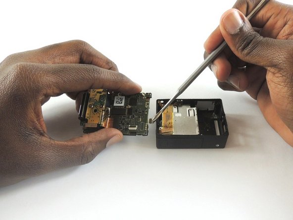
Insert a metal spudger between the back plastic housing and the camera board assembly. Working around the edge to be careful of the inner components, carefully remove the camera.
-
-
-
Este paso está sin traducir. Ayuda a traducirlo
-
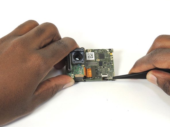
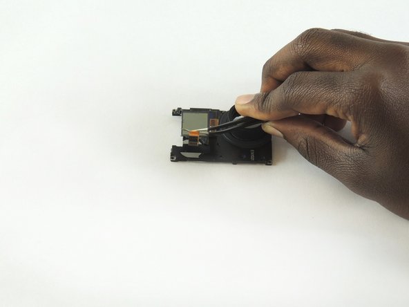
Using tweezers, remove the ribbon strip by pulling on it. This will remove the connection.
-
Push down on the three wires with the metal spudger and the clip will disconnect from the motherboard.
-
-
Este paso está sin traducir. Ayuda a traducirlo
-
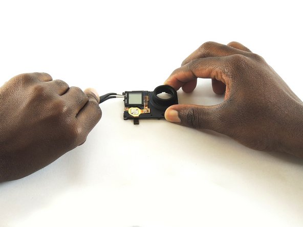
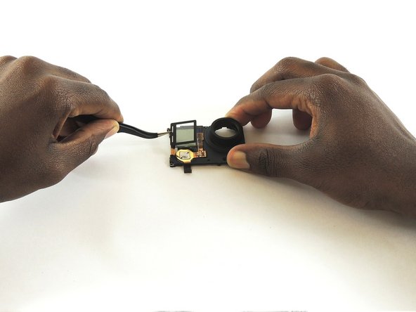
Open the clip that is located on the motherboard
-
Use a pair of tweezers to pull the ribbon from the clip
-
-
Este paso está sin traducir. Ayuda a traducirlo
-
Place the iOpener on the LCD screen cover to release the glue
-
Lift the covering of the LCD screen cover off with a pair of tweezers
-
-
Este paso está sin traducir. Ayuda a traducirlo
-
Use a pair of tweezers to lift the ribbon through the opening and lift all the way up to the LCD screen
-
-
Este paso está sin traducir. Ayuda a traducirlo
-
Place the iOpener on the LCD screen to remove the glue
-
Use a pair of tweezers to left the LCD screen off the device
-


Cancelar: No complete esta guía.
5 personas más completaron esta guía.
Equipo

USF Tampa, Team S2-G1, Sullivan Spring 2017 Miembro de USF Tampa, Team S2-G1, Sullivan Spring 2017
USFT-SULLIVAN-S17S2G1
4 Miembros
12 Guías creadas
2 comentarios
You got the screw locations on the front wrong. Bottom left is the shortest screw, where the battery compartment is. If you try putting one of the longer screws through their it'll bust into the battery compartment. Ask me how I know. And that's the one reason why I came to this, the one thing I couldn't remember.