Esta versión puede contener ediciones incorrectas. Cambie a la última instantánea verificada.
Qué necesitas
-
Este paso está sin traducir. Ayuda a traducirlo
-
Unscrew the two screws on the antenna unit using a torc-head screwdriver.
-
Gently pry open the antenna unit with your fingers.
-
-
Este paso está sin traducir. Ayuda a traducirlo
-
Slide out the inner casing attached to the antenna body.
-
Remove the rotating joint connecting the antenna casing to the main device:
-
Squeeze tweezers into the shown location and compress the spring.
-
Lift out the outer casing while keeping the spring compressed.
-
-
-
Este paso está sin traducir. Ayuda a traducirlo
-
Using a torx-head screwdriver, unscrew the two revealed screws that connect the front and back of the device.
-
-
Este paso está sin traducir. Ayuda a traducirlo
-
Insert the plastic opening tool into the center of the edge as shown in first picture.
-
Slide the plastic opening tool along the central gap of device, making sure that each edge is free, as shown in the second picture.
-
-
Este paso está sin traducir. Ayuda a traducirlo
-
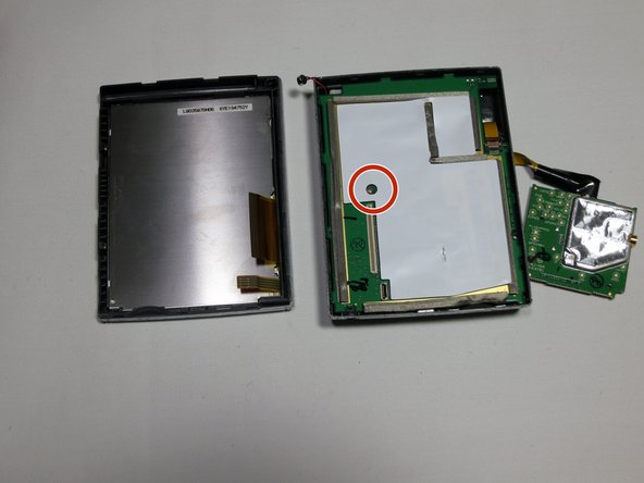
Detach the front display from the back panel of the device.
-
-
Este paso está sin traducir. Ayuda a traducirlo
-
Using tweezers, gently lift the microphone from its resting position to fully separate the device into two parts.
-
Finally, remove the screw that connects the motherboard to the back casing with a 3mm head driver.
-


Cancelar: No complete esta guía.
2 personas más completaron esta guía.
Equipo

Cal Poly, Team 13-65, Johann Spring 2013 Miembro de Cal Poly, Team 13-65, Johann Spring 2013
CPSU-JOHANN-S13S13G65
3 Miembros
6 Guías creadas