Esta versión puede contener ediciones incorrectas. Cambie a la última instantánea verificada.
Qué necesitas
-
-
Localiza el interruptor de liberación de la batería en la parte inferior del portátil.
-
-
Este paso está sin traducir. Ayuda a traducirlo
-
Remove the two 4.00 mm Phillips #1 screws from the battery tray.
-
-
Este paso está sin traducir. Ayuda a traducirlo
-
Insert the flat end of a spudger into the slot on the right side of the central control cover and pry it up.
-
Carefully pull the central control cover up along its edges.
-
-
Este paso está sin traducir. Ayuda a traducirlo
-
Peel back the silver tape securing the ribbon cable to the cover.
-
Pull the small brown latch on the ribbon cable connector out.
-
Disconnect the ribbon cable to completely free the central control cover.
-
-
Este paso está sin traducir. Ayuda a traducirlo
-
Remove the two 5.75 mm Phillips #1 screws securing the keyboard to the laptop.
-
Gently slide the keyboard towards the display until the tabs on its front side are free.
-
-
Este paso está sin traducir. Ayuda a traducirlo
-
Use a spudger to gently lift the ribbon cable retaining flap.
-
Disconnect the ribbon cable.
-
Shift the keyboard sideways enough to free one side from it's retaining tab. Then lift the keyboard away from the laptop.
-
-
-
Retira los dos tornillos Phillips nº 1 de 3,60 mm que sujetan el disco duro y la bandeja del disco duro.
-
Desliza el disco duro y la bandeja del disco duro fuera del portátil.
-
-
Este paso está sin traducir. Ayuda a traducirlo
-
Remove the 5.75 mm #1 Phillips screw securing the optical drive.
-
Pull the optical drive straight from the laptop.
-
-
-
Este paso está sin traducir. Ayuda a traducirlo
-
Remove/loosen the eight 4.80 mm Phillips #1 screws securing the bottom panel.
-
The screws may only need to be loosened, as they are generally retained by plastic washers.
-
Remove the bottom panel.
-
-
Este paso está sin traducir. Ayuda a traducirlo
-
Disconnect the five antennas from their respective cards.
-
De-route the antennas from their routing retainers.
-
-
Este paso está sin traducir. Ayuda a traducirlo
-
Remove the two 5.70 mm Phillips #1 screws securing the display assembly to the bottom case half.
-
-
Este paso está sin traducir. Ayuda a traducirlo
-
Use the flat end of a spudger to push the camera connector out of its socket. Alternate pushing on either side to evenly remove the connector.
-
Carefully release the connector from its retaining tabs.
-
-
Este paso está sin traducir. Ayuda a traducirlo
-
Push the antenna wires up through their hole in the bottom case half.
-
Release the antennas from their retaining tabs on the upper case.
-
-
Este paso está sin traducir. Ayuda a traducirlo
-
Disconnect the flat LCD ribbon cable by pulling it up by the tab.
-
Free the ribbon cable from its retaining clips.
-
-
Este paso está sin traducir. Ayuda a traducirlo
-
Remove the four 3.45 mm Phillips #1 screws securing the display assembly to the laptop chassis.
-
Remove the display assembly from the laptop.
-
-
Este paso está sin traducir. Ayuda a traducirlo
-
Remove the nine 5.75 mm Phillips #1 screws on the bottom side of the laptop.
-
Remove the two 5.70 mm Phillips #1 screws on the top side of the laptop.
-
-
Este paso está sin traducir. Ayuda a traducirlo
-
Use a spudger to pull the touch pad connector latch towards the ribbon cable.
-
Pull the ribbon cable out of the connector.
-
-
Este paso está sin traducir. Ayuda a traducirlo
-
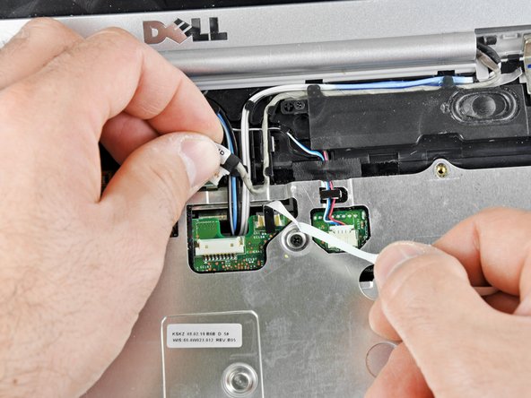
Use a spudger to pull the device status LED connector latch towards the ribbon cable.
-
Disconnect the device status LED ribbon cable.
-
-
Este paso está sin traducir. Ayuda a traducirlo
-
Release the ribbon cable in the upper left corner of the laptop from its retaining tabs.
-
Use a spudger to unplug the speaker connector at the top center of the laptop.
-
De-route the speaker wires from their retaining tabs.
-
-
Este paso está sin traducir. Ayuda a traducirlo
-
Use the flat end of a spudger to begin lifting the upper case at its front edge.
-
Lift the front edge of the case up until it comes free.
-
-
Este paso está sin traducir. Ayuda a traducirlo
-
Eject your ExpressCard or ExpressCard dust shield if you want to transfer it to the new ExpressCard cage. Eject the card by pressing it in until it clicks, releasing it, then sliding it out.
-
Remove the 3.80 mm Phillips #1 screw securing the ExpressCard cage.
-
Remove the two 3.70 mm Phillips #1 screws securing the ExpressCard cage.
-
Lift the ExpressCard cage out of its connector.
-
-
Este paso está sin traducir. Ayuda a traducirlo
-
Loosen the five #1 Phillips screws securing the heat sink and clean it with compressed air
-
Gently lift the heat sink from side indicated in the picture.
-
-
Este paso está sin traducir. Ayuda a traducirlo
-
Use a spudger to push the retaining latch of the central control button connector towards its cable.
-
Pull the cable out of the connector.
-
-
Este paso está sin traducir. Ayuda a traducirlo
-
Pull the retaining latch for the wireless sniffer cable out.
-
Remove the cable from the connector.
-
-
Este paso está sin traducir. Ayuda a traducirlo
-
Disconnect the fan cable connector by pulling it towards the fan with a spudger.
-
-
Este paso está sin traducir. Ayuda a traducirlo
-
Remove the four 3.70 mm Phillips #1 screws securing the motherboard to the lower case.
-
Gently peel the front bezel off.
-
Lift the motherboard out of the lower case.
-


Cancelar: No complete esta guía.
8 personas más completaron esta guía.

4 comentarios
Thank you for these directions!!! They made the tedious job of replacing the motherboard in my Inspiron 1525 much easier....only had to remove the motherboard one extra time to remove the modem and WIFI modem off the back as well as one cable that wasn't mentioned or needed to just get the motherboard out...Thanks again!!!
Hey, thanks for the kind words. I added a note on the last step as a reminder for folks to transfer any remaining components onto the new motherboard!
Thanks so much!!! This was perfect. I've never done anything like this before and you made it work!!!!