Saltar al contenido principal

Center Chassis Removal (Power Supply Attached)

Sólo Prerrequisito
Esta guía solo debería usarse como prerrequisito para otras guías. Por tanto, estará incompleta.

Qué necesitas

  1. Center Chassis Removal (Power Supply Attached), Uncover the back panel screws: paso 1, imagen 1 de 2 Center Chassis Removal (Power Supply Attached), Uncover the back panel screws: paso 1, imagen 2 de 2
    • Before you begin, completely power down and unplug all cables from your console.

    • Two stickers cover the back panel screws. You can remove the stickers without heating them, though it makes them much easier to remove cleanly.

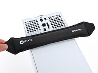
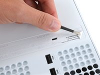
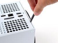
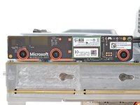
    • Heat an iOpener and lay it on the smaller sticker near the bottom of the back panel for two minutes.

    • Alternatively, you can use a hair dryer to heat the sticker.

  2. Center Chassis Removal (Power Supply Attached): paso 2, imagen 1 de 3 Center Chassis Removal (Power Supply Attached): paso 2, imagen 2 de 3 Center Chassis Removal (Power Supply Attached): paso 2, imagen 3 de 3
    • Use a pair of angled tweezers to remove the sticker hiding the first screw on the back panel, near the base.

  3. Center Chassis Removal (Power Supply Attached): paso 3, imagen 1 de 3 Center Chassis Removal (Power Supply Attached): paso 3, imagen 2 de 3 Center Chassis Removal (Power Supply Attached): paso 3, imagen 3 de 3
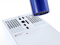
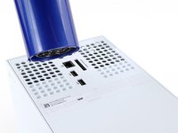
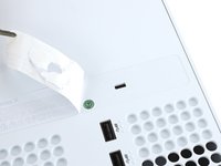
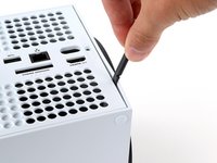
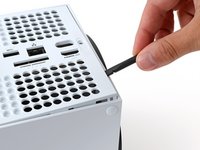
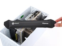
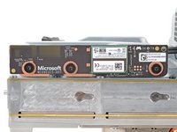
    • Use an iOpener or hair dryer to heat the larger sticker near the center of the back panel.

  4. Center Chassis Removal (Power Supply Attached): paso 4, imagen 1 de 3 Center Chassis Removal (Power Supply Attached): paso 4, imagen 2 de 3 Center Chassis Removal (Power Supply Attached): paso 4, imagen 3 de 3
    • Use the flat end of a spudger to scrape up a corner of the larger sticker until you can grip it with a pair of blunt tweezers.

    • Use blunt tweezers to peel back the sticker to reveal the second screw.

    • You only need to peel this sticker to where you can access the hidden screw. You don't need to pull it completely off.

    • Technically, these are tamper-evident stickers, but don't worry—Microsoft can't legally void your warranty, as long as you don't damage anything. Have fun!

  5. Center Chassis Removal (Power Supply Attached), Remove the back panel screws: paso 5, imagen 1 de 2 Center Chassis Removal (Power Supply Attached), Remove the back panel screws: paso 5, imagen 2 de 2
    Herramienta utilizada en este paso:
    Magnetic Project Mat
    $19.95
    • Throughout this repair, keep track of each screw and make sure it goes back exactly where it came from to avoid damaging your console.

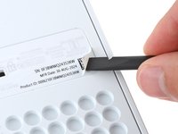
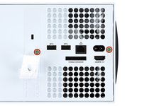
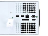
    • Use a T8 Torx driver to remove the two 7.4 mm‑long screws securing the back panel.

  6. Center Chassis Removal (Power Supply Attached), Unclip the back panel: paso 6, imagen 1 de 3 Center Chassis Removal (Power Supply Attached), Unclip the back panel: paso 6, imagen 2 de 3 Center Chassis Removal (Power Supply Attached), Unclip the back panel: paso 6, imagen 3 de 3
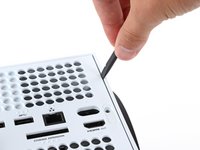
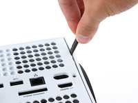
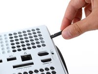
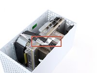
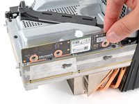
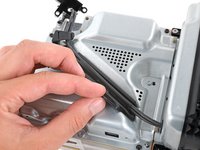
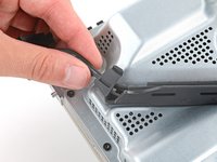
    • Insert the flat end of a spudger into the gap between the back panel and the shell, near the left side of the base.

    • Pry up the back panel to release it from the locking clips.

  7. Center Chassis Removal (Power Supply Attached): paso 7, imagen 1 de 3 Center Chassis Removal (Power Supply Attached): paso 7, imagen 2 de 3 Center Chassis Removal (Power Supply Attached): paso 7, imagen 3 de 3
    • Insert the flat end of a spudger into the gap between the back panel and the shell, near the right side of the base.

    • Pry up the back panel to release it from the locking clips.

  8. Center Chassis Removal (Power Supply Attached), Remove the back panel: paso 8, imagen 1 de 3 Center Chassis Removal (Power Supply Attached), Remove the back panel: paso 8, imagen 2 de 3 Center Chassis Removal (Power Supply Attached), Remove the back panel: paso 8, imagen 3 de 3
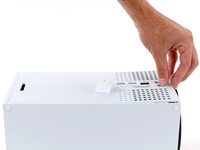
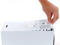
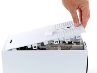
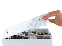
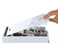
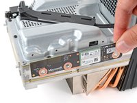
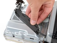
    • Grip the back panel at the opening you just created and pull it up and away from the shell to unclip the long edges.

    • During reassembly, press along the edges of the back panel to snap it into place.

  9. Center Chassis Removal (Power Supply Attached): paso 9, imagen 1 de 3 Center Chassis Removal (Power Supply Attached): paso 9, imagen 2 de 3 Center Chassis Removal (Power Supply Attached): paso 9, imagen 3 de 3
    • The back panel slots into a gap at the top of the shell.

    • Tilt the back panel up and pull it away from the top edge of the shell to release it from the gap.

    • Remove the back panel.

  10. Center Chassis Removal (Power Supply Attached), Remove the fan screws: paso 10, imagen 1 de 2 Center Chassis Removal (Power Supply Attached), Remove the fan screws: paso 10, imagen 2 de 2
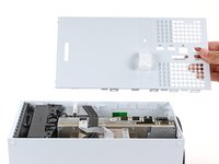
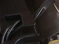
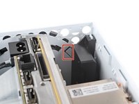
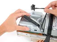
    • Use a T8 Torx driver to remove the three screws securing the fan to the center chassis:

    • One 10.3 mm‑long pancake screw

    • Two 9 mm‑long screws

  11. Center Chassis Removal (Power Supply Attached), Disconnect the fan cable: paso 11, imagen 1 de 3 Center Chassis Removal (Power Supply Attached), Disconnect the fan cable: paso 11, imagen 2 de 3 Center Chassis Removal (Power Supply Attached), Disconnect the fan cable: paso 11, imagen 3 de 3
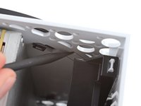
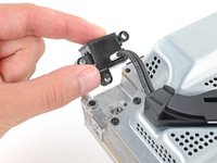
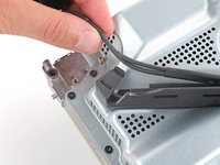
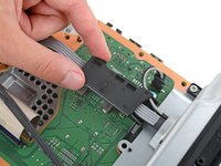
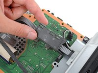
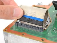
    • Use your fingernails or a pair of angled tweezers to firmly grip the edges of the fan cable connector.

    • Grip your tweezers close the connector to get a better grip.

    • Pull the connector straight out of the socket to disconnect it.

    • If you're having trouble, gently rock the connector side to side to loosen it.

    • Always pull cables by their connectors and not the wires themselves.

    • During reassembly, route the fan cable underneath its small cable guide on the fan housing so it doesn't interfere with the back panel.

  12. Center Chassis Removal (Power Supply Attached), Remove the fan: paso 12, imagen 1 de 3 Center Chassis Removal (Power Supply Attached), Remove the fan: paso 12, imagen 2 de 3 Center Chassis Removal (Power Supply Attached), Remove the fan: paso 12, imagen 3 de 3
    Herramienta utilizada en este paso:
    Dust Blower
    $18.99
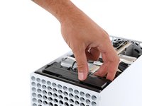
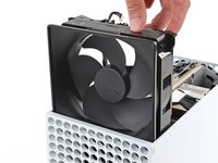
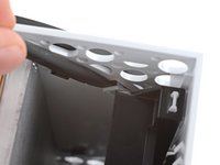
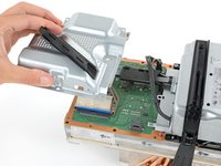
    • Slide the fan out of its slot to remove it.

    • During reassembly:

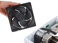
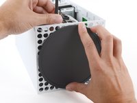
    • Before installing the fan, make sure it's clean! Use a dust blower or compressed air to blow off any dust or debris, and wipe the fan clean with a clean cloth.

    • Use a finger to keep the fan blades steady—it makes them easier to clean.

    • Note that the fan can only be installed one way—make sure Master Chief is facing you.

  13. Center Chassis Removal (Power Supply Attached), Unlatch the base: paso 13, imagen 1 de 3 Center Chassis Removal (Power Supply Attached), Unlatch the base: paso 13, imagen 2 de 3 Center Chassis Removal (Power Supply Attached), Unlatch the base: paso 13, imagen 3 de 3
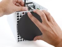
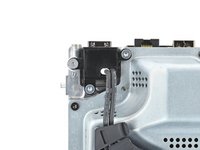
    • Use the flat end of a spudger to pry up the locking tab holding the base to the shell.

    • Keep the locking tab held open for the next step.

  14. Center Chassis Removal (Power Supply Attached), Twist and remove the base: paso 14, imagen 1 de 3 Center Chassis Removal (Power Supply Attached), Twist and remove the base: paso 14, imagen 2 de 3 Center Chassis Removal (Power Supply Attached), Twist and remove the base: paso 14, imagen 3 de 3
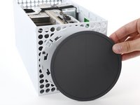
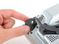
    • With the locking tab held open, grip the base and rotate it counterclockwise to unlock it from the shell.

    • Remove the base.

    • During reassembly, put the base tabs into their holes on the shell and twist clockwise until the base snaps into the interior locking tab.

    • When locked in place, the Hello from Seattle line will be parallel with the device's sides.

  15. Center Chassis Removal (Power Supply Attached), Disconnect the USB port cable: paso 15, imagen 1 de 3 Center Chassis Removal (Power Supply Attached), Disconnect the USB port cable: paso 15, imagen 2 de 3 Center Chassis Removal (Power Supply Attached), Disconnect the USB port cable: paso 15, imagen 3 de 3
    • The ribbon cables and their connectors are extremely fragile, so always open locking tabs gently and pull cables slowly.

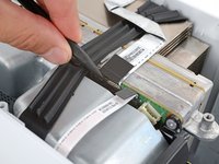
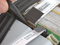
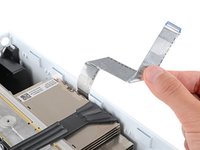
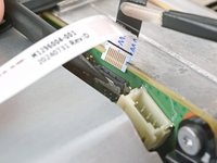
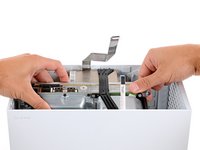
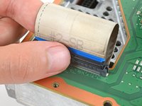
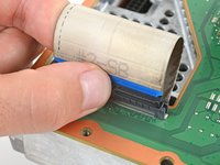
    • Use a spudger to flip open the metal locking tab on the USB port ribbon cable.

    • During reassembly, gently snap the metal locking tab back into place once the cable has been inserted.

  16. Center Chassis Removal (Power Supply Attached), Heat the USB port cable: paso 16, imagen 1 de 3 Center Chassis Removal (Power Supply Attached), Heat the USB port cable: paso 16, imagen 2 de 3 Center Chassis Removal (Power Supply Attached), Heat the USB port cable: paso 16, imagen 3 de 3
    • The USB port cable is secured to the chassis with two pieces of mild adhesive.

    • Use an iOpener or a hair dryer to heat the USB port cable.

  17. Center Chassis Removal (Power Supply Attached), Detach the USB port cable: paso 17, imagen 1 de 3 Center Chassis Removal (Power Supply Attached), Detach the USB port cable: paso 17, imagen 2 de 3 Center Chassis Removal (Power Supply Attached), Detach the USB port cable: paso 17, imagen 3 de 3
    Herramienta utilizada en este paso:
    Tesa 61395 Tape
    $2.99
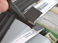
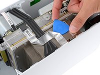
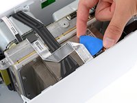
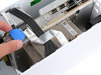
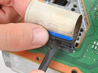
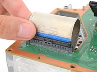
    • Slide an opening pick under the USB port cable to separate the adhesive securing it.

    • During reassembly, use thin double‑sided adhesive to secure the cable. If there's adhesive left and it's still sticky, you can reuse it. If you have a new cable, check it for pre‑installed adhesive and remove any liners.

  18. Center Chassis Removal (Power Supply Attached): paso 18, imagen 1 de 3 Center Chassis Removal (Power Supply Attached): paso 18, imagen 2 de 3 Center Chassis Removal (Power Supply Attached): paso 18, imagen 3 de 3
    • Use a pair of tweezers to gently pull up on the black plastic pull tab to disconnect the USB port cable.

    • Pull only on the pull tab, not the cable itself.

    • Move the USB port cable out of the way of the chassis.

  19. Center Chassis Removal (Power Supply Attached), Disconnect the power button cable: paso 19, imagen 1 de 3 Center Chassis Removal (Power Supply Attached), Disconnect the power button cable: paso 19, imagen 2 de 3 Center Chassis Removal (Power Supply Attached), Disconnect the power button cable: paso 19, imagen 3 de 3
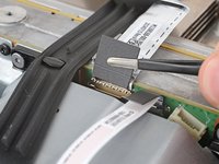
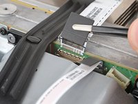
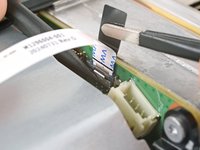
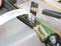
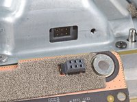
    • Use the pointed end of a spudger to depress the metal tab on the side of the power button cable's board connector.

    • With the metal tab depressed, use a pair of tweezers to pull up on the pull tab to disconnect the power button cable from the center chassis.

    • Pull only on the pull tab, not the cable itself.

    • Don't pull on the cable without depressing the metal tab, otherwise you risk damaging either the cable or the connector.

    • During reassembly, the cable should lightly "snap" into place when inserted.

  20. Center Chassis Removal (Power Supply Attached), Remove the chassis screws: paso 20, imagen 1 de 2 Center Chassis Removal (Power Supply Attached), Remove the chassis screws: paso 20, imagen 2 de 2
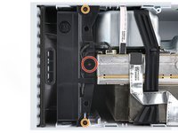
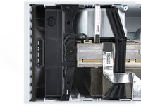
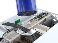
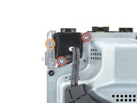
    • Use a T8 Torx driver to remove the three 7.4 mm‑long green screws securing the center chassis assembly to the shell.

  21. Center Chassis Removal (Power Supply Attached), Remove the chassis: paso 21, imagen 1 de 3 Center Chassis Removal (Power Supply Attached), Remove the chassis: paso 21, imagen 2 de 3 Center Chassis Removal (Power Supply Attached), Remove the chassis: paso 21, imagen 3 de 3
    • The center chassis assembly is aligned to the bottom of the shell with guide pegs. These pegs will need to slide out of their slots to allow the chassis to be lifted out.

    • Grip the chassis and pull it towards the top of the shell, uncoupling the guide pegs from the shell.

    • Use two hands to lift out the chassis to remove it from the shell.

    • During reassembly:

    • Make sure neither of the ribbon cables get pinched as you lower the center chassis into the shell.

    • Use the alignment pegs and cutouts to properly orient the chassis in the shell:

    • Two pegs on the chassis with cutouts on the bottom of the shell.

    • Three pegs in the shell with cutouts on the chassis.

  22. Center Chassis Removal (Power Supply Attached): paso 22, imagen 1 de 2 Center Chassis Removal (Power Supply Attached): paso 22, imagen 2 de 2
    Herramienta utilizada en este paso:
    Dust Blower
    $4.99
    • Gently place the chassis heatsink-side down on a clean work surface.

    • During reassembly, this is a good point to clean the heatsink fins of any dust, dirt, or debris that may have built up over time. Use a dust blower or compressed air to clear out the fins.

  23. Center Chassis Removal (Power Supply Attached), Remove the antenna board screws: paso 23, imagen 1 de 2 Center Chassis Removal (Power Supply Attached), Remove the antenna board screws: paso 23, imagen 2 de 2
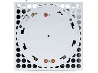
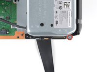
    • Use a T8 Torx driver to remove the three 9.6 mm‑long screws securing the antenna board to the center chassis.

  24. Center Chassis Removal (Power Supply Attached), Remove the accessory antenna board: paso 24, imagen 1 de 3 Center Chassis Removal (Power Supply Attached), Remove the accessory antenna board: paso 24, imagen 2 de 3 Center Chassis Removal (Power Supply Attached), Remove the accessory antenna board: paso 24, imagen 3 de 3
    • Grip the top right corner of the antenna board and pull it directly away from the center chassis to disconnect it.

    • During reassembly, align the board's connector with the port on the center chassis and press to reconnect.

  25. Center Chassis Removal (Power Supply Attached), Remove the power cable port: paso 25, imagen 1 de 2 Center Chassis Removal (Power Supply Attached), Remove the power cable port: paso 25, imagen 2 de 2
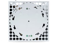
    • Use a T8 Torx driver to remove the three screws securing the power cable port to the chassis:

    • Two 13.1 mm‑long screws

    • One 35 mm‑long screw

  26. Center Chassis Removal (Power Supply Attached): paso 26, imagen 1 de 2 Center Chassis Removal (Power Supply Attached): paso 26, imagen 2 de 2
    • Lift the power connector out of its recess in the chassis.

  27. Center Chassis Removal (Power Supply Attached), De-route the power cables: paso 27, imagen 1 de 2 Center Chassis Removal (Power Supply Attached), De-route the power cables: paso 27, imagen 2 de 2
    • Unlatch and open the lid on the power cable's plastic guide.

  28. Center Chassis Removal (Power Supply Attached): paso 28, imagen 1 de 2 Center Chassis Removal (Power Supply Attached): paso 28, imagen 2 de 2
    • Lift the power cable out from underneath the extra section of the cable guide.

  29. Center Chassis Removal (Power Supply Attached), Remove the board shield: paso 29, imagen 1 de 2 Center Chassis Removal (Power Supply Attached), Remove the board shield: paso 29, imagen 2 de 2
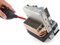
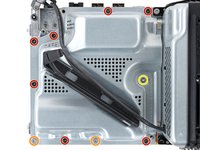
    • Use a T8 Torx driver to remove the ten screws securing the board shield:

    • Seven 8.7 mm‑long screws

    • Two 35 mm‑long screws

    • These screws are very tight and may take significant force to loosen.

    • One 13 mm‑long screw

  30. Center Chassis Removal (Power Supply Attached): paso 30, imagen 1 de 3 Center Chassis Removal (Power Supply Attached): paso 30, imagen 2 de 3 Center Chassis Removal (Power Supply Attached): paso 30, imagen 3 de 3
    • Hold the power supply cable out of the way and lift the board shield straight up to remove it.

  31. Center Chassis Removal (Power Supply Attached), Disconnect the power supply cables: paso 31, imagen 1 de 3 Center Chassis Removal (Power Supply Attached), Disconnect the power supply cables: paso 31, imagen 2 de 3 Center Chassis Removal (Power Supply Attached), Disconnect the power supply cables: paso 31, imagen 3 de 3
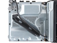
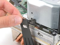
    • Open the lid on the power supply's plastic cable guide.

  32. Center Chassis Removal (Power Supply Attached): paso 32, imagen 1 de 3 Center Chassis Removal (Power Supply Attached): paso 32, imagen 2 de 3 Center Chassis Removal (Power Supply Attached): paso 32, imagen 3 de 3
    • Always pull cables by their connectors and not the wires themselves.

    • Use your fingers to pinch the power supply's 10‑pin power connector, so the locking tab opens outward.

    • With the locking tab open, lift the connector straight up and out of its socket.

  33. Center Chassis Removal (Power Supply Attached), Disconnect the interconnect cable: paso 33, imagen 1 de 3 Center Chassis Removal (Power Supply Attached), Disconnect the interconnect cable: paso 33, imagen 2 de 3 Center Chassis Removal (Power Supply Attached), Disconnect the interconnect cable: paso 33, imagen 3 de 3
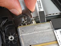
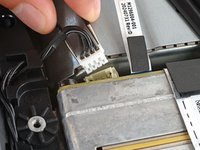
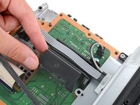
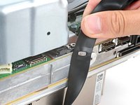
    • Use your fingers to pinch the locking tab in the center of the interconnect cable connector.

    • While pinching the tab, insert the flat end of a spudger between the top of the socket and the connector's tab.

    • Twist the spudger to lift the connector out of its socket until the clip in the center disengages.

  34. Center Chassis Removal (Power Supply Attached): paso 34, imagen 1 de 2 Center Chassis Removal (Power Supply Attached): paso 34, imagen 2 de 2
    • Use your fingers to pull the connector straight up and out of its socket.

    • During reassembly, insert the interconnect cable connector into its socket and press down on both edges until the connector snaps into place.

  35. Center Chassis Removal (Power Supply Attached), Unlatch the chassis strap: paso 35, imagen 1 de 3 Center Chassis Removal (Power Supply Attached), Unlatch the chassis strap: paso 35, imagen 2 de 3 Center Chassis Removal (Power Supply Attached), Unlatch the chassis strap: paso 35, imagen 3 de 3
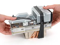
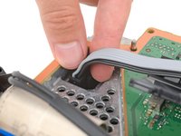
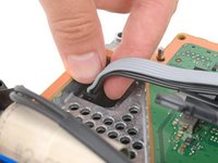
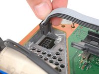
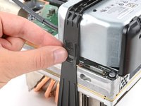
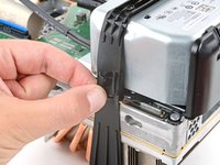
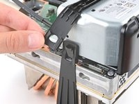
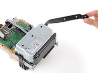
    • Pull the rubber strap down and away from the chassis to unlatch it.

  36. Center Chassis Removal (Power Supply Attached): paso 36, imagen 1 de 3 Center Chassis Removal (Power Supply Attached): paso 36, imagen 2 de 3 Center Chassis Removal (Power Supply Attached): paso 36, imagen 3 de 3
    • Pull the chassis strap off its three alignment posts and unlatch it from the sides of the power supply.

    • You can leave the strap under the chassis or remove it.

    • During reassembly, make sure the nubs in the middle of the strap go unto their cutouts on the heat sink fins.

  37. Center Chassis Removal (Power Supply Attached), Remove the silver power supply screws: paso 37, imagen 1 de 2 Center Chassis Removal (Power Supply Attached), Remove the silver power supply screws: paso 37, imagen 2 de 2
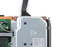
    • Use a T8 Torx driver to remove the three 35 mm‑long silver screws from the power supply—leave the fourth black screw in place.

  38. Center Chassis Removal (Power Supply Attached), Remove the center chassis: paso 38, imagen 1 de 3 Center Chassis Removal (Power Supply Attached), Remove the center chassis: paso 38, imagen 2 de 3 Center Chassis Removal (Power Supply Attached), Remove the center chassis: paso 38, imagen 3 de 3
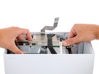
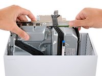
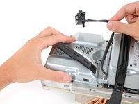
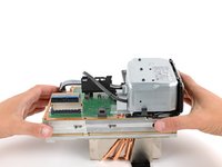
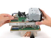
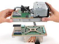
    • Grip the edges of the center chassis (not the power supply) and lift it off the motherboard and heatsink assembly, routing the interconnect cable through its cutout.

Linea de Meta

Spencer Day

Miembro Desde 09/14/22

95,960 Reputación

662 Guías creadas

Equipo

iFixit Miembro de iFixit

Staff

Miembros de 118

19,648 Guías creadas

0Guía Comentarios

Agregar Comentario

Ver Estadísticas:

Ultimas 24 horas: 0

Ultimos 7 días: 4

Ultimos 30 días: 25

Todo El Tiempo: 31